cCJ System Plus Duo 55 Installation and Operating Instruction Manual Including User Instructions
Chaffoteaux et Maury Ltd., as a leading manufacturer of domestic and commercial water heating appliances, as well as domestic unvented direct and indirect storage cylinders, is committed to providing high quality products and a first class after sales service. If it is necessary to contact an engineer, then telephone your local Chaffoteaux Service Centre. Advice on installation or servicing can also be obtained by contacting the Chaffoteaux Customer Services Department.
The installation of this appliance must be carried out by a licenced installer and who is a CORGI Registered person or other competent person and in accordance with the requirements of the Gas Safety (Installation and Use) Regulations and the Building Regulation Approved Document G3.
Customer Care ............................................... .I Guarantee ...................................................... .I Commissioning ........................................ 16-l 7 DHW .................................................................. 16 Central Heating .................................................. 16 Lighting the Boiler.. ............................................. 17 Statutory Requirements .................................. .2 Post Commissioning ...............
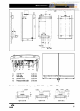
BRITONY SYSTEM PLUS 60 Appliance category .................................... Cat II 2H3+ Heat input C/H & DHW Maximum in kW.. ................................ 20.22 Maximum in Btu/h ............................... 69005 Heat output C/H & DHW Maximum in kW.. ................................ Maximum in Btu/h ............................... C/H circuit pressures Min operating in bar in ib/in* Max operating in bar in ib/in2 Safety discharge in bar.. .................................................
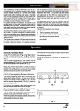
, , , , , , , , , , , , , , , , , , , , , , , , , , , , , , , , , , , , , , J K L N 0 3 : i Ir 67 j I - I I I I I I I I I I I I I I -+--I I -8 +380+ Heating flow H.W. flow Gas supply Heating return Pressure relief outlet TypeClZorC42 e b ~~+~ 022mm 022mm 022mm 022mm I I 015mm The boiler is suitable for the 4 flue types: *type Cl2 or C42 C&M -.
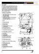
The Cylinder The Chaffoteaux et Maury BRITONY DUO 55 is designed for use as an unvented storage cylinder heated indirectly by a BRITONY SYSTEM PLUS 60 boiler. The cylinder is supplied with a safety controls pack and expansion vessel to allow it to be connected to the main cold water supply. The cylinder is stainless steel with a high power coil. It is contained within a white case insulated with a preformed polystyrene jacket. Location of components 1. 2. 3. 4. 5.
44. Temperature selector Flow and Return flexible pipes (not visible) 45. Temperature and pressure relief valve 46. Chassis 47. DHW expansion vessel 48. Cylinder 49. Pressure test point The Safety Controls 19 21 20 22 26 Pack To enable the cylinder to comply with the current regulations it is supplied with a safety controls pack.
The Chaffoteaux et Maury BRITONY DUO 55 is a combination of an unvented stainless steel storage cylinder heated indirectly by a fanned flued sealed system boiler within matching outer cases. It benefits from the high efficiency provided by the modern low water content BRITONY System Plus 60 boiler and a high power coil within the cylinder. A combination providing very fast reheating of the hot water.
Central Heating Mode To be able to supply central heating, the selector switch (19 Fig. 1) must be in ‘~~~~ 3 position. This will be confirmed by the green indicator light 0 (22 Fig. 1). When there is a demand for heating (either from the room thermostat or the external programmer) and the boiler temperature control is calling for heat. The pump starts and at a flow rate of 4ltr/min the central heating flow switch operates allowing the ignition sequence to begin. The first stage solenoid (12a Fig.
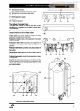
Planning Safety Notice Installation must be carried out by a suitably qualified installer and in accordance with current regulations and codes of practice. Please ensure that you are familiar with the installation requirements as well as the relevant British Standards and Statutory Regulations (see page 2) before commencing work. Only the safety valves supplied with the cylinder should be used. Location The DUO 55 can be installed on any suitable internal wall.
It can also be used to ensure the correct spacing of kitchen cabinets etc. The template is fixed to the wall and used to locate the fixing holes for the boiler hanging bracket, the pre-piping bracket and the cylinder chassis. It should also be used to locate the centre of the flue hole. There is space to allow pipes to pass behind the boiler without the need for an additional spacer. Fig. 4 Drill and plug the wall and secure the hanging bracket using the screws provided.
Locate the thermostat phial in its sleeve using the clip and rubber plug supplied. See Fig. 8. Connecting the Cylinder The main water supply should be carefully flushed through, to clear any debris, before connecting to the cylinder. For cylinders fitted to the right of the boiler Connect the long flexible tube (A Fig. 10) between the hot water isolating valve (32 Fig. 10) and the inlet of the coil (42 Fig. 10) using the tail (D Fig. 10).
Wiring Making the electrical connections To gain access to the electrical connections, press tabs (P Fig 12) to release the catches on either side of the boiler and pivot the electrical box forward. Remove the two retaining screws (Afig 12), lift the cover and turn over to reveal an interface PCB and connecting block (Fig 13). Connect the live and neutral wires to the connector (D Fig 13) on the interface PCB leaving sufficient earth wire to connect to the main earthing point.
Discharge pipe from temperature and pressure relief valve to tundish Safety Valves The DUO 55 has a pressure relief valve fitted to the boiler and a temperature and pressure relief valve fitted to the cylinder. It is most important that they are terminated below the boiler and over the tundish which in turn should terminate safely outside the premises (see Fig. 14). It is recommended that the tundish is installed directly below the discharge pipe from the temperature and pressure relief valve (37 Fig. 15).
3 Valve outlet size Gll2 Minimum size of discharge pipe 15mm Minimum size of discharge pipe from tundish Maximum resistance allowed, expressed as a length of straight pipe (i.e. no elbows or bends) Resistance created by each elbow or bend 22mm Up to 9m 0.8m 28mm Up to 18m l.Om 35mm Up to 27m 1.4m From boiler pressure dzLP--: relief valve and pressure relief valve ; : :’ ‘: ~ iL =: Fig.
DHW Filling the Cylinder Ensure that all fittings and valves are correctly installed and are water tight Flush all debris from the supply pipes before connecting to the cylinder Open the furthest hot water tap from the DUO 55 cylinder Open the mains water inlet valve and allow the cylinder to fill.
Lighting . . . . . . . . . . . . . the Boiler Connect gas pressure gauge to set test point (43 Fig. 19). Turn on the gas supply and boiler gas tap (27 Fig. 18). Check all boiler connections for gas soundness. Ensure electrical supply is on. Ensure all external controls are calling for heat. Turn selector switch (19 Fig. 20) to heating and hot water position Turn the boiler thermostat to maximum (21 Fig.20). The boiler will light. Allow the boiler to heat system.
Flue The boiler must be installed so that the flue terminal is exposed to the free passage of external air at all times. It must not be allowed to discharge into another room or space such as an outhouse or closed lean-to. The minimum acceptable clearances are shown below: A Directly below an opening, window etc.
System Pressure The boiler is suitable for sealed systems only. The maximum working pressure for the appliance is 3 bar. All fittings and pipework connected to the appliance should be of the same standard. Flushing and Water Treatment The performance of the appliance could be impaired by system debris or the effects of corrosion. The system must be flushed thoroughly to remove metal filings, solder, machining oils and other fluxes and greases before connecting the boiler.
be reset by turning a screw (D Fig. 22) anti-clockwise to open the by-pass using the chart below for guidance. If used on a system with thermostatic radiator valves, the flow rate with thermostatic valves closed should be adjusted to at least 100 Vhr. The chart below indicates the residual head of the pump available for the system. Expansion Vessels Boiler The expansion vessel is pre-charged to 0.7 bar (lOlb/it-?). The vessel is suitable for systems up to 145 litres capacity.
In order to ensure that the BRITONY DUO 55 continues to operate efficiently and safely, it is essential that the boiler and the cylinder are maintained annually. Servicing and repairs should only be carried out by a competent engineer Any part replaced should be genuine Chaffoteaux et Maury spare parts l l Routine l Maintenance 7. Strainer While the cylinder is partially drained the strainer can be removed and cleaned Refill and repressurise the system as set out in the commissioning instructions. 3.
Switching On 1. Check that the gas service tap is opened at the gasmeter and main power is on. 2. Check that pressure in central heating system is above 0.7 bar and below 2.5 bar with the pressure gauge @ (26). 3. Open the gas tap (27) by turning from right to left.& 4. The boiler is now ready to use. Heating 1. Turn selector switch (19) fully clockwise to position ‘1111 The green ‘power on’ indicator (‘J will light. 2.
I Deterioration flow or pressure at hot tap I 1 I Cold water from hot taps I I 1 Remove and clean c Check operation of Boiler 3 port valve 1 I + Boiler not operating 4 Reset and check operation of cylinder thermostat
L I I”” Ei8 I
Discharge of Water from the Expansion Relief Valve
Chaffoteaux et Maury are contunuously improving their products and therefore reserve the right to change specifications without prior notice and accepts no liability for any errors or omission in the information contained in this document. 0 Chaffoteaux & Maury Limited 1999 Chaffoteaux & Maury Limited, Trench Lock, Trench, Telford, Shropshire TFI 4SZ.