
Technical data


5
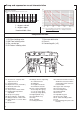
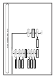
N° Designation Wiring colours
13.
-Overheat sensor Brown
14. -Electrical box
14a.
-Regulation PCB
14b. -Ignitor Red, Black
14c. -Fuse 1.25 A
14d. -Fuse 2A
14e. -Power PCB
14f. -Room thermostat
14g. -Mains 230V 50 Hz
18. -Pressure switch 2: Black P: Orange
1: White
27. -Spark electrodes White
28. -Ionisation probe White
30.
-Security solenoid (grey) Grey
31. -2/3 gas stage solenoid (black) Black
32.
-1/3 gas stage solenoid (blue) Blue
35. -Pump
37.
-C/H thermistor Violet
38. -DHW thermistor Green
42. -3 way valve White, Yellow, Orange
44. -DHW flow switch Brown
45. -C/H flow switch Red
51. -Fan Brown, Blue
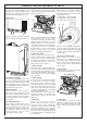
The following adjustments are available on the regulation PCB. To
gain access to them, pivot down electrical box, remove the rear
cover and the rear panel of electrical box, unplug connectors from
regulation PCB and pull it toward you.
Heating output limitation :
- Functioning without limitation
plug C on "P MAX"
- Functioning at 1/3 gas rate only plug C on "P 1/3"
Burner functioning:
- Regulation available 3/3, 1/3, 0 plug D on "NOR"
- Functioning at full gas rate only plug D on "TUR"
C
D
ELECTRICAL WIRING continuation ADJUSTMENTS ON CONTROL PCB
ROUTINE SERVICING
To ensure continued efficient operation of
the appliance, it is recommended that it is
checked and serviced as necessary at
regular intervals. The frequency of servic-
ing will depend upon the particular instal-
lation condition and usage, but in general,
once a year should be adequate.
It is the law that any service work must be
carried out by a competent person such
as your local Chaffoteaux Service Centre,
British Gas or other CORGI registered
personnel in accordance with the current
Gas Safety (Installation and Use)
Regulations.
The service schedule should include
the following operations:
- Check the pressure in the system by
checking the reading on the pressure
guage (No. 18 Control Panel - Page 3).
- Check the correct operation of the appli
-
ance
(see Page 4 - Domestic Hot Water
Mode and Central Heating Mode).
- Check the correct operation of the gas
controls.
- Check the functions of the safety con
-
trols.
- Check combustion chamber insulation
panels for damage.
- Clean the burner.
- Clean the heat exchanger.
- Check the burner manifold injectors.
- Clean gas and water filters.
- Check expansion vessel charge pres
-
sure.
- Clean and check operation of safety
valve.
Additional Procedures that may be
necessary:
- Check burner pressure and gas flow
rates.
- Check that the fan blades are clean.
- Check, clean and replace components as
necessary.
- Carry out combustion test utilising the test
points in the flue turret.
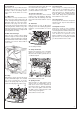
SUGGESTED SEQUENCE for SERVIC-
ING
Before disconnecting or removing any
parts, isolate the gas and electricity sup-
plies. Ensure that the appliance is cool.
(for detail please see section on Parts
Removal and Replacement)
Preliminary Checks
- Remove outer case
- Check the system pressure is at least
0.7 bar cold
- Check operation of 1/3 and 2/3 solenoids.
- Check that the burner is extinguished fully
when both solenoids are closed in both
DHW and C/H modes.
- Test ionisation functions and check that
lockout occurs by turning off gas tap.
- Whilst boiler is operating, check operation
of primary fl
ow switch by closing heating
fl
ow valve and by pass screw (turn clock-
wise) noting the number of turns so that it
may be reset correctly.
Temperature regulation for both C/H and
DHW circuits are controlled by 2 thermis-
tors. The C/H knob allows the adjustment
of temperature between 35 and 85°C. The
DHW temperature is limited to 60°C. DHW
and C/H thermistors are identical and
interchangeable.
Resistance value are
-5000 Ω at 25 °C
-2631 Ω at 40°C
-620 Ω at 80°C
-255 Ω at 110°C
REGULATION
Flow in both D.H.W. and Heating circuits
are detected by 2 flow switches. A piston
with a magnet at the top operates a REED
switch. The piston is lifted by flow rates
listed below :
Flow rate threshold :
D.H.W.
120 l/h ±20 l/h
C/H 250 l/h ±20 l/h
FLOW SWITCHES
The air flow rate is detected by a pressure
differential created by a venturi located in
the fl
ue duct.
ON threshold ∆P > 130 Pa
OFF threshold ∆P < 100 Pa
AIR PRESSURE SWITCH