
User`s manual


6
3.1 Description of the Appliance
SX water heaters are sealed electronic water heaters, with electronic ignition and ionisation safety devices, they have a modulat-
i
ng burner and are connected to the mains water supply; they provide domestic hot water. Their self-contained combustion
chambers with fans for the intake of external air and the extraction of combustion products, allow them to operate totally inde-
pendently from the room in which they are installed.
12
3
7
2
9
13
4
5
6
1
10
11
14
8
15
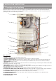
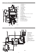
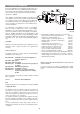
Main components :
1.
FRAME
including the bar f
or suspending the w
ater heater
.
2. SEALED CHAMBER BASE, which, together with the casing, forms the combustion chamber
3. PRODUCTS EXTRACTION SET which includes the extractor body, fan, air pressure switch and coaxial outlet duct Ø 60-100
4. FAN for expelling the combustion gases to the outside through the tube Ø60 and to take in air from outside the chamber
5.
HEA
TING BOD
Y
made of copper
6.
BURNER
made of stainless steel and with a b
lue flame which works with natural gas or Butane/Propane. Distributor fitted with
injectors that correspond to each type of gas
7. ELECTRODES for ignition and flame sensor which works by ionisation
8.
GAS
V
ALVE
fitted with tw
o saf
ety valves, manual power rating selection, automatic power modulation according to the flow of
w
ater and gradual progressive lighting of the burner.
9. WATER VALVE fitted with an automatic water flow regulator and with a manual temperature selector
10. ELECTRICAL POWER SUPPLY AND CONTROL: Supplies the water heater with 1.5 V from the mains supply at 220-230 V
a.c.
Supplies the f
an and, through the air pressure meter
, controls the extraction of the combustion products.
11.
ELECTR
ONIC CIRCUIT
f
or igniting the flame and controlling it b
y means of ionisation.
12. AIR PRESSURE SWITCH which cuts off the intake of gas to the burner if waste products are not expelled correctly
13. COAXIAL OUTLET Ø 60-100
14. ELECTRICAL SUPPLY CABLE
15.
HEA
T EXCHANGER
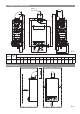
3 INSTALLATION INSTRUCTIONS
FIG.5