HPH1 High Performance Variable Speed Operator INSTALLATION MANUAL HPH1, 1.25 HP (120V/240V Single Phase & 230V 3 Phase) HPH2, 1.25 HP (460V/575V Three Phase, via stepdown transformer) NADA AND THE U.S. UL D C US NOT FOR RESIDENTIAL USE • Please read this manual and the enclosed safety materials completely, prior to installation and use! • This product is to be installed and serviced by a trained door systems technician ONLY.
SAFETY INFORMATION IMPORTANT NOTES: • BEFORE attempting to install, operate or maintain the commercial door operator, you must read and fully understand this manual and follow all safety instructions. • DO NOT attempt repair or service of a commercial door operator unless you are an Authorized Service Technician. • A commercial door operator should only be installed on a properly balanced door only. Ensure door is properly balanced prior to installation.
TABLE OF CONTENTS ALL PAGE NUMBERS AND HEADERS TEMPORARY PENDING FINAL PASS SAFETY INFORMATION 3 OPERATOR 4-9 Overview . . . . . . . . . . . . . . . . . . . . . . . . . . . . . . . . . . . . 4-6 Carton Inventory . . . . . . . . . . . . . . . . . . . . . . . . . . . . . . . . 6 Operator Specifications . . . . . . . . . . . . . . . . . . . . . . . . 7-10 INSTALLATION . . . . . . . . . . . . . . . . . . . . . . . . . . . . . . . 11-13 Determine Mounting Location . . . . . . . . . . . . . . . . . . . . .
THIS DATA AND THE FOLLOWING PAGE MAY NOT BE ACCURATE OR IS PENDING. PLEASE PROVIDE ACCURATE INFORMATION FOR THE HPH1 OPERATOR SPECIFICATIONS MODEL HPH1 HPH2 HP VOLTAGE PHASE 1.25 HP 120V 1 1.25 HP 240V 1 1.25 HP 230V 3 1.25 HP 460V 3 1.25 HP 575V 3 AMPS MANUAL HOIST: Single action manual hoist with integral manual operation protection circuit. CABLE TENSION MONITOR: Detects ANY slack that may occur in the cables and will reverse the door, eliminating service calls.
OPERATOR SPECIFICATIONS (CONT.) (These values are based on a 3/4" curtain thickness - for more door thicknesses, please visit https://www.LiftMaster.
OVERVIEW ART NOT FINAL CARTON INVENTORY Before beginning installation, confirm all components are enclosed.
OVERVIEW (CONT.) To prevent possible SERIOUS INJURY or DEATH: • DO NOT connect electric power until instructed to do so. • If the door lock needs to remain functional, install an interlock switch. • ALWAYS call an Authorized Service Technician if door binds, sticks, or is out of balance. An unbalanced door may NOT reverse when required. • NEVER try to loosen, move, or adjust doors, door springs, cable, pulleys, brackets, or their hardware.
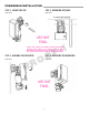
INSTALLATION On HTH operators, the motor head can be mounted on either the right or left side of the door, as shown in the diagram below. ART NOT FINAL INSTALLING THE POWERHEAD NOTE: Before lifting operator be sure to install the hoist chain. Attach the mounting bracket to operator prior to lifting into position. Do not tighten fasteners. 1. Attach a 1/2¨-13 eye bolt to the uppermost mounting hole of the wall brace. 2.
POWERHEAD INSTALLATION STEP 1: LOCATE THE KEY STEP 2: OPERATOR DISTANCE NEED TEXT NEED TEXT ART NOT FINAL SHOULD THE TEXT ON THE PREVIOUS PAGE BE DISTRIBUTED THROUGH THESE STEPS? IF SO, WHICH STEPS GO WITH WHICH IMAGE? ARE NEW HEADERS REQUIRED? (SEE ‘LOCATE KEY’ WHICH SEEMS TO HAVE NO INSTRUCTIONS ASSIGNED) STEP 3: ALIGNING THE OPERATOR STEP 4: MOUNTING THE OPERATOR NEED TEXT NEED TEXT ART NOT FINAL 9
JUNCTION BOX WIRING TONY TO PROVIDE A PICTURE WITH INFORMATION ON WHERE WIRING WILL COME IN AND WHAT EVERYTHING IS Wire mains input power here Connect the earth ground wire to the green wire using the wire nut provided. Connect Line and Neutral wires to the terminal block as marked (L, N) ART NOT FINAL CALLOUTS TO BE APPLIED WHEN COMPLETE 10 Locate the black 4-Wire cable and the black 2-Wire cable with connectors fastened to one end.
INSTALLATION INSTALLING THE CABLE TENSION MONITOR THE CABLE TENSION MONITORS MUST BE CONNECTED AND PROPERLY INSTALLED BEFORE THE DOOR OPERATOR WILL MOVE IN THE DOWN DIRECTION. 1. Make sure the door cable is approximately 3/4"-1" (19-20 mm) from the mounting surface. Door adjustments or shimming may be required to achieve proper depth for the door cable.
INSTALLATION WIRING THE CABLE TENSION MONITOR (CONT.) 4. Locate the black 4-wire data cable with a green (color needs to be confirmed) 5 pin connector at one end. 5. Locate the black 2-wire Power Cable with a green (color is tbd) 2 pin connector at one end. 6. Locate the grey 4-wire encoder cable attached to the operator. 7. Pull the encoder cable into the junction box through the cord grip (on back side of junction box - include diagram). 8.
INSTALLATION To prevent possible SERIOUS INJURY or DEATH from electrocution: • Be sure power is NOT connected BEFORE installing the door control station. To prevent possible SERIOUS INJURY or DEATH from a closing door: • Install the door control within sight of the door, out of reach of small children, at a minimum height of 5 feet (1.5 m) above landings, steps, or any other adjacent walking surface, and away from ALL moving parts of the door.
CONTROLLER SPECIFICATIONS 1/2" knockout 1/2" conduit Auxiliary expansion board NC Com NO NC Com NO NC Com Display board Up button (Open?) Stop/enter button Aux board connector Down button (Close?) Cellular modem (avail.
FIELD WIRING THIS AND THE NEXT THREE PAGES ARE PLACE HOLDERS FOR DIAGRAMS SHOWING A STEP BY STEP WIRING OF THE CONTROLLER, AND IS VERY DIFFERENT FROM THE VFOH.
FIELD WIRING FPO 16
FIELD WIRING FPO 17
FIELD WIRING WIRING INCOMING POWER TO THE CONTROLLER 1. Check the controller mains input power requirement from the controller to be installed. (120V or 240V) WARNING: Ensure input voltage selection switch is in the correct position. 2. Route conduit using Fig. 1 for selecting the recommended hole to bring the mains input power wiring inside the enclosure. 3.
FIELD WIRING 3-PHASE STEP-DOWN TRANSFORMER WIRING 1. Make sure the transformer is fully installed and secured with proper hardware. WARNING 575V 3-Phase 2. Make sure all conduit routing is complete and terminated as needed. WARNING 460V 3-Phase WARNING 230V 1-Phase Blue Yellow Orange 3. The stepdown transformer accepts a 3-phase input and has a single phase output. The transformer primary connects to the L1 and L2 terminals. L3 is not connected and wiring mains power to L3 is optional.
ENTRAPMENT PROTECTION LIFTMASTER MONITORED ENTRAPMENT PROTECTION (LMEP) To prevent possible SERIOUS INJURY or DEATH from a closing door: • Be sure power is NOT connected to the door operator BEFORE installing the LiftMaster Monitored Entrapment Protection Device(s). • The door MUST be in the fully opened or closed position BEFORE installing the LiftMaster Monitored Entrapment Protection Device(s).
PROGRAMMING IMPORTANT SAFETY INSTRUCTIONS TO REDUCE THE RISK OF SEVERE INJURY OR DEATH: 1. READ AND FOLLOW ALL WARNINGS AND INSTRUCTIONS. 2. ALWAYS keep remote controls out of reach of children. NEVER permit children to operate or play with door control push buttons or remote controls. 3. ONLY activate a door when it can be seen clearly, it is properly adjusted and no obstructions exist in the path the door will travel. 4.
PROGRAMMING To prevent possible SERIOUS INJURY or DEATH: • Disconnect electric power BEFORE performing ANY adjustments or maintenance. • ALL maintenance MUST be performed by a trained door systems technician. • Please wait several seconds for capacitors to discharge and for display to go out.
PROGRAMMING MENUS To enter program mode from the front panel buttons, press and hold Stop, Open and Close together for 3 seconds. The screen will display "Control By Buttons". The Stop button functions as Enter and the Open and Close buttons function as Up and Down. If no button is pressed for 30 seconds the controller will exit this programming mode. The internal Menu/Enter, Up, and Down buttons are always active for programming. The main menu is displayed as graphic icons on the display.
PROGRAMMING NEW MENU TREE TO COME Idle Screen Display Readout Emergency Jog Express Menu System Status Radio Mode Operating Mode Limit Setup System Config Overview Learn Operating Mode Quick Setup Timers LMEP Erase Sec. +2.0 Freq. Profiles Closed Outputs Erase myQ Optr.
PROGRAMMING PROFILE SELECTION Operating Mode To simplify installation this operator contains preset defaults called profiles. Each profile contains the manufacturer’s recommended initial settings for a particular operator model. A B C D These profiles allow an installer to quickly set up a door. After a profile has been loaded the controller can be further adjusted to meet a specific customer’s requirements as needed, such as timer settings, input configurations and other options.
PROGRAMMING OPERATING MODES THIS PAGE IS BEING UPDATED PER ANDERS MELBERG This operator is programmed to function in one of six different operating modes. B2 Mode: • Works with a 3-Button Control Station wired and 3-Button Radio control, momentary to open,stop, and close. • Single Button Control and Single Button Radio momentary to open, stop, close, and stop & reverse. • LMEP device required to be learned and connected for downward movement.
PROGRAMMING PROGRAMMING / FREQUENCY PROFILES The controller contains three preconfigured frequency profiles that control the motor speed, as well as the acceleration and deceleration ramps. These profiles cannot be manually altered. If accelerations or decelerations are too high, reduce the frequency profile to a lower setting. THIS SECTION REQUIES NEW Medium is the default setting for all profiles.
PROGRAMMING RADIO The controller has a built in Security+ 2.0® radio receiver, that can program up to 90 remote control devices and up to 30 keyless entry devices. PROGRAMMING REMOTE CONTROLS Select Radio from the main menu (this action will require installer passcode entry). From the Radio menu, select LEARN. Select the desired function: SBC, Open, Close, Stop or myQ® Device. When the screen displays “Looking for Devices”, press the desired transmitter button or press the learn button on your myQ® Device.
PROGRAMMING myQ® SMART FACILITY ACCESS One Platform to manage access for Unlimited Facilities, Users and Vehicles myQ® Smart Facility Access allows you to control all your access points in the facility from the myQ® website application from anywhere. Monitor & control your vehicular access doors, gated entry locations & even dock positions from a universal platform.
DETERMINE AND SET OPERATING MODE OPERATING MODE SHEETS PENDING CONSOLIDATION Select the operating mode for your application from the menu in the controller, see page 24.
DETERMINE AND SET OPERATING MODE (CONTINUED) WIRING TYPE DEVICE ACTION OPEN button is pressed momentarily CLOSE button is pressed momentarily Front panel buttons (membrane) and 3-Button Control Station STOP button is pressed momentarily OPEN button is held (constant pressure) B2 Momentary contact to open,close and stop, plus wiring for sensing device to reverse and auxiliary devices to open and close with open override.
DETERMINE AND SET OPERATING MODE (CONTINUED) WIRING TYPE DEVICE ACTION STATE RESPONSE Operator at OPEN limit Operator at CLOSE limit Door opening OPEN button is pressed momentarily Door closing Door at Open Mid-Stop Door stopped during open or close cycle Operator at OPEN limit Operator at CLOSE limit Door opening CLOSE button is pressed momentarily Door closing Door at Open Mid-Stop Door stopped during open or close cycle Operator at OPEN limit Operator at CLOSE limit Front panel Door opening buttons(
DETERMINE AND SET OPERATING MODE (CONTINUED) WIRING TYPE DEVICE ACTION STATE RESPONSE Operator at OPEN limit Operator at CLOSE limit Door opening OPEN button is pressed momentarily Door closing Door at Open Mid-Stop Door stopped during open or close cycle Operator at OPEN limit Operator at CLOSE limit Door opening CLOSE button is pressed momentarily Door closing Door at Open Mid-Stop Door stopped during open or close cycle Operator at OPEN limit Operator at CLOSE limit Front panel Door opening buttons(
DETERMINE AND SET OPERATING MODE (CONTINUED) WIRING TYPE DEVICE ACTION OPEN button is pressed momentarily CLOSE button is pressed momentarily 3-Button Control Station STOP button is pressed momentarily OPEN button is held (constant pressure) CLOSE button is held (constant pressure) D1 Constant pressure to open and close with wiring for sensing device to stop.
DETERMINE AND SET OPERATING MODE (CONTINUED) WIRING TYPE DEVICE ACTION OPEN button is pressed momentarily CLOSE button is pressed momentarily 3-Button Control Station STOP button is pressed momentarily OPEN button is held (constant pressure) CLOSE button is held (constant pressure) E2 Momentary contact to open with override and constant pressure to close. Release of close button will cause door to reverse (roll-back feature) plus wiring for sensing device to reverse.
NOTE: THIS TROUBLESHOOTING GUIDE WAS TAKEN DIRECTLY FROM THE PDF SUPPLIED BY JUSTIN PEART. ALMOST NO CHANGES WERE MADE TO THE CONTENT AND THE TERMINOLOGY MAY BE INCORRECT. PLEASE CHECK. TROUBLESHOOTING If an error occurs, the idle screen is replaced by a screen showing the error code and a description of the error. An example error code display is shown below.
TROUBLESHOOTING Error Code: Description: Level: Cause: Check: F08 Configuration not found. Reset to factory setting. F09 System was restarted F10 UPWARD force curve is missing Force sensing in UPWARD direction is activated. But force curve in UPWARD direction is not stored. Execute teachin drive. F11 DOWNWARD force curve is missing Force sensing in DOWNWARD direction is activated. But force curve in DOWNWARD direction is not stored. Execute teach-in drive.
TROUBLESHOOTING Error Code: Description: F84 Light grid error Level: Light grid continuously triggered, or test cannot be executed. • Object in door area • Cable defect • Light grid incorrectly aligned • Light grid not ready for operation Cause: Check: F90 Error in Uart initialization: Line used Error in cabling F91 Error in position encoder message: position outside of valid range • Wrong encoder set • Error in communication cable F92 Time out error when receiving position econder message.
MAINTENANCE MAINTENANCE SCHEDULE Check at the intervals listed in the following chart: To avoid SERIOUS personal INJURY or DEATH: • Disconnect electric power BEFORE performing ANY adjustments or maintenance. • ALL maintenance MUST be performed by a trained door systems technician.
WIRING DIAGRAMS PAGE NOT FINAL PENDING FINAL INFO FROM TEAM Cadena de No Entrada polispasto utilizado 0V OMS 0V analógica +24V +24V CIERRE SBC +24V 0V +24V AUX2 0V RPM AUX1 0V probado Térmica APERTURA PARADA TDFT Borde de seguridad 1 2 3 4 5 6 7 8 9 10 11 12 13 14 15 16 17 18 19 20 21 22 23 COM NO NC 24 25 26 Please note that the terminal block is numbered for easy identification.
ACCESSORY WIRING DIAGRAM NON MONITORED SAFETY EDGES White (NC) OV 2 Black (Common) ANALOG INPUT 3 SAFETY EDGE * 1 * 1 2 XX 4 Blue (–) Blue (–) +24V 5 Brown (+) RPM 6 PAGE NOT FINAL PENDING FINAL INFO FROM TEAM OV OMS 7 AUX1 8 OPEN *Pin 11 - Output 1 (Green) CLOSE *Pin 12 - Output 2 (Blue) STOP 3BCS 50-HERK2 LC-36A NOTE: Only use 12V for encoder connection Do not connect more than three wires at one terminal; if needed, use wire nuts.
SERVICE PARTS SERVICE KIT K41-0160 K41-0164 K41-0161 K41-0162 K41-0163 K41-0156 K41-0157 NUMBER HPH1/HPH2 HPH1/HPH2 HPH1/HPH2 HPH1/PH2 HPH1/HPH2 HPH1/HPH2 HPH1/HPH2 DESCRIPTION Control Box Cover Control Box Back Control board Display board with Screen Control Box 3 Button Assembly CTM Left Hand CMT Right Hand Motor Head: K41-0165 K41-0166 K41-06167 K41-06168 K41-06169 K41-06170 K41-06171 K41-06172 K41-06173 K41-06174 K41-06175 K41-06176 DH1 & HDH2 DH1 & HDH2 DH1 & HDH2 DH1 & HDH2 DH1 & HDH2 DH1 & HDH2 D
OPERATOR DIMENSIONS FRONT VIEW 9.37" 23.8 cm SIDE VIEW 14.53" 36.9 cm NEED BRACKET 26.19" 66.
WARRANTY LIFTMASTER LIMITED WARRANTY LiftMaster (“Seller”) warrants to the first retail purchaser of this product, for the residence in which this product is originally installed, that it is free from defects in materials and/or workmanship for a specific period of time as defined below (the “Warranty Period”). The warranty period commences from the date of purchase.