
User Manual

Multi-GAP Mode
To put the unit in Multi-GAP (Gate Access
Panel) Mode, place dipswitch #1 DOWN
(towards the circuit board) placing the unit
into “Passive” mode. This unit will now act
as an accessory to an “Active” GAP or
“Active” MiniGAP2 module within an Oracle
System Network, customarily used at a side
or back entrance. Any accessories that had
been previously activated to a “Passive”
MiniGAP2 will have to be re-activated to
the “Active” GAP or MiniGAP2 unit.
In Multi-GAP mode, when activating
multiple GCU’s, each additional GCU must
be activated as the #1 unit to the “Active”
GAP or MiniGAP2. After any additional GCU
has been activated, it will then need to be
set as the #2
or #3 GCU by using chart #2
below, to correspond with the “Passive”
MiniGAP2, set using chart #1 below.
Note: If you have 2 or 3 GCU’s and you fail to
give each one their own Identity (1,2, or 3) and
leave each GCU set as unit #1, the units will fail
to function.
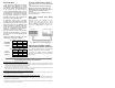
Changing GCU dipswitches #1&2 in the Gate
Control Unit sets the GCU’s Identity.
GCU
IDENTITY
MiniGAP2
SW1
MiniGAP2
SW2
1 off off
2 on off
3 off on
GCU
IDENTITY
GCU
SW1
GCU
SW2
1 off off
2 on off
3 off on
Clearing the Mini-GAP2’s Memory
Note: Clear the memory only for a new Multi-GAP mode
set-up.
Clear the MiniGAP2’s memory by switching
dipswitch #1 DOWN and holding down the
LEARN button for ten seconds. It will sound a
tone indicating the memory has been
cleared.
Note: A MiniGAP2 in “Active” mode does NOT need to
have its memory cleared.
Basic Gate Control Unit (GCU)
Installation
Mount the Oracle Gate Controller near your
Automatic Gate Opener’s control motor. Most
gate motors have simple relay connections (often
labeled COMMON and CYCLE) that connect to
the two large OPEN/CLOSE relay outputs of the
GCU.
(See Gate Control Module installation manual
for complete Gate Controller Configuration.)
Adjusting the MiniGAP2 Speaker
volume and Microphone Sensitivity
To increase the Outdoor Intercom’s volume, switch
dipswitch #4 UP (away from the circuit board).
To increase the Outdoor Intercom’s microphone
sensitivity, switch dipswitch #3 UP (away from the
circuit board).
Troubleshooting and Frequently Asked Questions
Nothing Happens. The MiniGAP2 Does Not Function
Make sure that the Intercom has fresh batteries in it. When you press the CALL button, you should hear a tone. If
the units have power but do not communicate, they may need to form a network. Press the LEARN button on each unit
that needs to form a network and they will beep in response.
You may need to clear their memory and re-teach them.
Dipswitch #1 is normally UP (away from the circuit board). In the DOWN position it will not operate unless it is
taught to an Oracle Network, as a passive unit (See MULTI-GAP MODE).
The MiniGAP2 is Not Getting the Expected Transmission Range
Trees, metal, electrical wiring or other electrical devices directly between units can limit the range, as can having it
mounted on a tree, masonry, or metal surface.
I hear a warbling two-tone error sound when I activate the Gate Controller?
The MiniGAP2 unit is not communicating with the GCU. The GCU may be out of range. If the units work properly when
close together, the GCU may need to be mounted higher off the ground or on a different surface. Metal, trees, or
masonry cause the most interference.
If the units do not work when close together, the MiniGAP2 has not mated with that GCU. Double-check the GCU’s ID
(as set with dipswitches 1 & 2, and re-teach it.
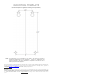
MiniGAP2
Dipswitch
Settings
GCU
Dipswitch
Settings
#1
#2