® GARAGE DOOR OPENER Model 1265LMC 1/2 HP For Residential Use Only Owner’s Manual ■ Please read this manual and the enclosed safety materials carefully! ■ Fasten the manual near the garage door after installation. ■ The door WILL NOT CLOSE unless the Protector System® is connected and properly aligned. ■ Periodic checks of the opener are required to ensure safe operation. ■ The model number label is located on the front panel of your opener.
TABLE OF CONTENTS Introduction Pages 2-5 Adjustment Safety symbol and signal word review ........................2 Preparing your garage door ........................................3 Tools needed ...............................................................3 Planning .....................................................................4 Carton inventory..........................................................5 Hardware inventory .....................................................
Preparing your garage door WARNING Before you begin: • Disable locks. • Remove any ropes connected to garage door. • Complete the following test to make sure your garage door is balanced and is not sticking or binding: 1. Lift the door about halfway as shown. Release the door. If balanced, it should stay in place, supported entirely by its springs. 2. Raise and lower the door to see if there is any binding or sticking.
Planning Identify the type and height of your garage door. Survey your garage area to see if any of the conditions below apply to your installation. Additional materials may be required. You may find it helpful to refer back to this page and the accompanying illustrations as you proceed with the installation of your opener. SECTIONAL DOOR INSTALLATION Horizontal and vertical reinforcement is needed for lightweight garage doors (fiberglass, steel, aluminum, door with glass panels, etc.).
Carton Inventory Your garage door opener is packaged in two cartons which contain the motor unit and all parts illustrated below. Accessories will depend on the model purchased. If anything is missing, carefully check the packing material. Parts may be stuck in the foam. Hardware for installation is also listed below.
WARNING CAUTION ASSEMBLY STEP 1 Attach the T-Rail to the Motor Unit To avoid serious damage to opener, ONLY use screws mounted in top of motor unit. To avoid installation difficulties, do not run the garage door opener until instructed to do so. • Remove the two washered screws mounted in top of motor unit. • Position T-rail at a 45˚ angle to opener so one hole in T-rail and motor unit line up. • Thread one of the washered screws part way in.
ASSEMBLY STEP 3 Outer Nut Tighten the Chain Lock Washer Inner Nut To Tighten Outer Nut • Spin the inner nut and lock washer down the threaded shaft, away from the trolley. • To tighten the chain, turn outer nut in the direction shown. As you turn the nut, keep the chain from twisting. • When the chain is approximately 1/2" above the base of the T-rail at its midpoint, re-tighten the inner nut to secure the adjustment. Sprocket noise can result if chain is either too loose or too tight.
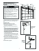
INSTALLATION STEP 1 Determine the Header Bracket Location Finished Ceiling Vertical Centerline Header Wall 2x4 WARNING Structural Supports WARNING To prevent possible SERIOUS INJURY or DEATH: • Header bracket MUST be RIGIDLY fastened to structural support on header wall or ceiling, otherwise garage door might not reverse when required. DO NOT install header bracket over drywall. • Concrete anchors MUST be used if mounting header bracket or 2x4 into masonry.
ONE-PIECE DOOR WITHOUT TRACK 1. Close the door and mark the inside vertical centerline of your garage door. Extend the line onto the header wall above door, as shown. If headroom clearance is minimal, you can install the header bracket on the ceiling. See page 10. If you need to install the header bracket on a 2x4 (on wall or ceiling), use lag screws (not provided) to securely fasten the 2x4 to structural supports as shown. 2. Open your door to the highest point of travel as shown.
INSTALLATION STEP 2 Install the Header Bracket Wall Mounting Holes You can attach the header bracket either to the wall above the garage door, or to the ceiling. Follow the instructions which will work best for your particular requirements. Do not install the header bracket over drywall. If installing into masonry, use concrete anchors (not provided). CEILING MOUNT ONLY The nail hole is for positioning only. You must use lag screws to mount the header bracket.
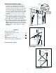
INSTALLATION STEP 3 Attach the T-Rail to the Header Bracket • Position the opener on the garage floor below the header bracket. Use packing material as a protective base. NOTE: If the door spring is in the way you’ll need help. Have someone hold the opener securely on a temporary support to allow the rail to clear the spring. • Position the rail bracket against the header bracket. • Align the bracket holes and join with a clevis pin as shown. • Insert a ring fastener to secure.
WARNING CAUTION INSTALLATION STEP 4 Position the Opener To prevent damage to garage door, rest garage door opener rail on 2x4 placed on top section of door. Follow instructions which apply to your door type as illustrated. SECTIONAL DOOR OR ONE-PIECE DOOR WITH TRACK A 2x4 laid flat is convenient for setting an ideal doorto-rail distance. • Raise the opener onto a stepladder. You will need help at this point if the ladder is not tall enough.
WARNING INSTALLATION STEP 5 Hang the Opener To avoid possible SERIOUS INJURY from a falling garage door opener, fasten it SECURELY to structural supports of the garage. Concrete anchors MUST be used if installing any brackets into masonry. CAUTION Two representative installations are shown. Yours may be different. Hanging brackets should be angled (Figure 1) to provide rigid support. On finished ceilings (Figure 2), attach a sturdy metal bracket to structural supports before installing the opener.
WARNING WARNING INSTALLATION CAUTION STEP 6 WARNING Install the Door Control To prevent possible SERIOUS INJURY or DEATH from electrocution: • Be sure power is not connected BEFORE installing door control. • Connect ONLY to 24 VOLT low voltage wires. To prevent possible SERIOUS INJURY or DEATH from a closing garage door: • Install door control within sight of garage door, out of reach of children at a minimum height of 5 feet, and away from all moving parts of door.
INSTALLATION STEP 7 Install the Lights and Lenses Lens Guide INSTALL THE LIGHTS • Install a 75 watt maximum light bulb in each socket. The lights will turn ON and remain lit for approximately 4-1/2 minutes when power is connected. Then the lights will turn OFF. • If the bulbs burn out prematurely due to vibration, replace with a Garage Door Opener bulb. Lens Tab Lens Slot INSTALL THE LENSES • Slide lenses into guides. Snap bottom tabs into lens slots. • Reverse the procedure to remove the lenses.
INSTALLATION WARNING STEP 9 WARNING Electrical Requirements To prevent possible SERIOUS INJURY or DEATH from electrocution or fire: • Be sure power is not connected to the opener, and disconnect power to circuit BEFORE removing cover to establish permanent wiring connection. • Garage door installation and wiring MUST be in compliance with all local electrical and building codes. • NEVER use an extension cord, 2-wire adapter, or change plug in any way to make it fit outlet. Be sure the opener is grounded.
WARNING INSTALLATION STEP 10 Install The Protector System® • Be sure power is not connected to the garage door opener BEFORE installing the safety reversing sensor. • To prevent SERIOUS INJURY or DEATH from a closing garage door: – Correctly connect and align the safety reversing sensor. This required safety device MUST NOT be disabled. – Install the safety reversing sensor so beam is NO HIGHER than 6" above garage floor.
INSTALLING THE BRACKETS Be sure power to the opener is disconnected. Install and align the brackets so the sensors will face each other across the garage door, with the beam no higher than 6" above the floor. They may be installed in one of three ways, as follows. Figure 1 DOOR TRACK MOUNT (RIGHT SIDE) Door Track Lip Garage door track installation (preferred): • Slip the curved arms over the rounded edge of each door track, with the curved arms facing the door.
MOUNTING AND WIRING THE SAFETY SENSORS • Slide a 1/4"-20x1/2" carriage bolt head into the slot on each sensor. Use wing nuts to fasten sensors to brackets, with lenses pointing toward each other across the door. Be sure the lens is not obstructed by a bracket extension. See Figure 4. • Finger tighten the wing nuts. • Run the wires from both sensors to the opener. Use insulated staples to secure wire to wall and ceiling. • Strip 1/4" of insulation from each set of wires.
WARNING CAUTION INSTALLATION STEP 11 Fasten the Door Bracket To prevent damage to garage door, reinforce inside of door with angle iron both vertically and horizontally. Follow instructions which apply to your door type as illustrated below or on the following page. A horizontal reinforcement brace should be long enough to be secured to two or three vertical supports. A vertical reinforcement brace should cover the height of the top panel. Figure 1 shows one piece of angle iron as the horizontal brace.
ONE-PIECE DOORS Please read and comply with the warnings and reinforcement instructions on the previous page. They apply to one-piece doors also. • Center the door bracket on the top of the door, in line with the header bracket as shown. Mark either the left and right, or the top and bottom holes. • Metal Doors: Drill 3/16" pilot holes and fasten the bracket with the 1/4"-14x5/8" self-threading screws provided.
INSTALLATION STEP 12 Inner Trolley Connect Door Arm to Trolley Outer Trolley Follow instructions which apply to your door type as illustrated below and on the following page. SECTIONAL DOORS ONLY • Make sure garage door is fully closed. Pull the emergency release handle to disconnect the outer trolley from the inner trolley. Slide the outer trolley back (away from the door) about 2" as shown in Figures 1, 2 and 3.
ALL ONE-PIECE DOORS 1. Assemble the door arm: • Fasten the straight and curved door arm sections together to the longest possible length (with a 2 or 3 hole overlap). • With the door closed, connect the straight door arm section to the door bracket with the 5/16"x1-1/4" clevis pin. • Secure with a ring fastener. 2. Adjustment procedures: On one-piece doors, before connecting the door arm to the trolley, the travel limits must be adjusted.
WARNING ADJUSTMENT STEP 1 Adjust the UP and DOWN Travel Limits Without a properly installed safety reversal system, persons (particularly small children) could be SERIOUSLY INJURED or KILLED by a closing garage door. • Incorrect adjustment of garage door travel limits will interfere with proper operation of safety reversal system. • If one control (force or travel limits) is adjusted, the other control may also need adjustment. • After any adjustments are made, the safety reversal system MUST be tested.
WARNING ADJUSTMENT STEP 2 Adjust the Force Without a properly installed safety reversal system, persons (particularly small children) could be SERIOUSLY INJURED or KILLED by a closing garage door. • Too much force on garage door will interfere with proper operation of safety reversal system. • NEVER increase force beyond minimum amount required to close garage door. • NEVER use force adjustments to compensate for a binding or sticking garage door.
WARNING ADJUSTMENT STEP 3 Test the Safety Reversal System Without a properly installed safety reversal system, persons (particularly small children) could be SERIOUSLY INJURED or KILLED by a closing garage door. • Safety reversal system MUST be tested every month. • If one control (force or travel limits) is adjusted, the other control may also need adjustment. • After ANY adjustments are made, the safety reversal system MUST be tested.
OPERATION IMPORTANT SAFETY INSTRUCTIONS WARNING To reduce the risk of severe injury or death: CAUTION 1. READ AND FOLLOW ALL WARNINGS AND 8. If one control (force or travel limits) is adjusted, the INSTRUCTIONS. 2. ALWAYS keep remote controls out of reach of children. NEVER permit children to operate or play with garage door control push buttons or remote controls. 3. ONLY activate garage door when it can be seen clearly, it is properly adjusted, and there are no obstructions to door travel. 4.
Using the Wall-Mounted Door Control THE MULTI-FUNCTION DOOR CONTROL Press the push bar to open or close the door. Press again to reverse the door during the closing cycle or to stop the door while it's opening. B) To operate one door using all three buttons on the hand-held remote: You may program the remote to Open Stop open the door with the large button, Close stop the door’s movement with the middle button, and close the door with the third button.
Care of Your Opener Having a Problem? LIMIT AND FORCE ADJUSTMENTS: Weather conditions may cause some minor changes in door operation requiring some LIMIT CONTROLS readjustments, particularly during the first year of operation. (Left side panel) Pages 24 and 25 refer to the limit and force adjustments. Only a screwdriver is required. Follow the instructions carefully. FORCE CONTROLS Repeat the safety reverse test (Back panel) (page 26) after any adjustment of limits or force. 1.
11. The door reverses for no apparent reason and opener lights blink for 5 seconds after reversing: • Check the safety reversing sensor. Remove any obstruction or align the receiving eye. See Installation Step 10. Having a Problem? (Continued) 6. The garage door opens and closes by itself: • Be sure that all remote control push buttons are off. • Remove the bell wire from the door control terminals and operate from the remote only.
PROGRAMMING Your garage door opener has already been programmed at the factory to operate with your hand-held remote control. The door will open and close when you press the large push button. Below are instructions for programming your opener to operate with additional Security✚ remote controls. To Add an Additional Hand-held Remote Control USING THE “LEARN” BUTTON USING THE MULTI-FUNCTION DOOR CONTROL 1 3 2 9 1 7 1 3 9 1 7 3 5 5 KG KG 2 LOCK LIGHT 1 2 1.
To Add or Change a Keyless Entry PIN Note: Your new Keyless Entry must be programmed to operate your garage door opener. USING THE “LEARN” BUTTON USING THE MULTI-FUNCTION DOOR CONTROL 1 3 2 9 1 7 1 3 9 1 7 3 5 5 KG KG 2 LOCK LIGHT 1. Press and release the “learn” button on motor unit. The learn indicator light will glow steadily for 30 seconds. 1 2 NOTE: This method requires two people if the Keyless Entry is already mounted outside the garage. KG 1.
REPAIR PARTS Rail Assembly Parts 5 1 3 4 2 6 KEY NO. PART NO. DESCRIPTION 1 2 3 4 5 6 4A1008 41A4813 41A3489 183B99 41D3484 83A11-2 Master link kit Chain pulley bracket Complete trolley assembly One-piece T-rail Full chain assembly Rail grease Installation Parts 4 2 1 3 KEY PART NO. NO.
Motor Unit Assembly Parts 1 2 4 3 6 7 6 20 16 19 8 18 9 10 17 5 3 7 (Down) Contact Brown Wire 13 15 16 LIMIT SWITCH ASSY. 11 14 Grey Wire DN UP Drive Gear Center Limit Contact KEY NO. PART NO.
ACCESSORIES 1702LMC Outside Quick Release: Required for a garage with NO access door. Enables homeowner to open garage door manually from outside by disengaging trolley. 982LMC Plug-In Light Control: Enables homeowner to turn on a lamp, television or other appliance from car, bedside, or anywhere in the home with a remote. 1708LMC 8 Foot Complete Rail: To allow an 8 foot door to open fully. 973LMC SECURITY✚ 3-Channel Remote Control: With key ring and Velcro fastening strip.
LIFTMASTER SERVICE IS ON CALL HOW TO ORDER REPAIR PARTS OUR LARGE SERVICE ORGANIZATION SPANS AMERICA Selling prices will be furnished on request or parts will be shipped at prevailing prices and you will be billed accordingly. INSTALLATION AND SERVICE INFORMATION IS AS NEAR AS YOUR TELEPHONE SIX DAYS A WEEK. SIMPLY DIAL OUR TOLL FREE NUMBER: WHEN ORDERING REPAIR PARTS, ALWAYS GIVE THE FOLLOWING INFORMATION: • PART NUMBER • PART NAME 1-800-654-4736 HOURS: (Central Std. Time) 6:00 A.M. TO 7:00 P.M.
® OUVRE-PORTE DE GARAGE Modèle 1265LMC 1/2 HP Pour résidences seulement Manuel d'instructions ■ Lire attentivement ce manuel ainsi que les consignes de sécurité! ■ Après la pose, accrocher ce manuel près de la porte de garage pour s'y reporter ultérieurement. ■ La porte NE SE FERMERA PAS si le Système PROTECTOR® n'est pas branché et réglé correctement. ■ Pour un bon fonctionnement en toute sécurité de cet ouvre-porte de garage, le vérifier et le régler périodiquement.
TABLE DES MATIÈRES Introduction Pages 2-5 Revue des symboles de sécurité et des mots de signalement . . . . . . Préparation de votre porte de garage Outils nécessaires . . . . . . . . . . . . . . Planning . . . . . . . . . . . . . . . . . . . . . Inventaire des boîtes d'emballage . . . . Inventaire des fixations . . . . . . . . . . . . . . . . . . Sur le montage Pages 6-7 . . . . . . . . . . . . . . . . . . . . . . . . . . . . . . . . . . . . . . . . . . . . . . . . . . . . . . Réglages .2 .
Préparation de votre porte de garage AVERTISSEMENT Avant de commencer : • Inactiver les serrures. • Retirer toute corde raccordée à la porte de garage. • Procéder au contrôle suivant pour s’assurer que la porte est bien équilibrée et qu’elle ne coince pas : 1. Soulever la porte à moitié, comme il est illustré, puis la relâcher. Si elle est équilibrée, elle devrait rester en place, entièrement supportée par ses ressorts. 2. Ouvrir et fermer la porte pour s'assurer qu'elle ne force pas.
Planning Identifier le type et la hauteur de votre porte de garage. Examiner la région du garage pour noter si l’une des conditions ci-après s’applique à votre installation. Des matériaux supplémentaires peuvent être nécessaires. Il vous sera peut-être utile de vous reporter à cette page et aux illustrations qui l’accompagnent en procédant à la pose de l’ouvre-porte. PLAFOND FINI Une cornière et des fixations sont requises. Se reporter à la page 13.
Inventaire des boîtes d’emballage Votre ouvre-porte de garage est emballé dans deux boîtes qui contiennent le moteur et toutes les pièces illustrées ci-après. Les accessoires dépendront du modèle acheté. S’il manque quoi que ce soit, vérifier soigneusement le matériel d’emballage. Les pièces peuvent être coincées dans la mousse. Les ferrures de montage sont également indiquées ci-après.
AVERTISSEMENT ATTENTION MONTAGE - 1RE OPÉRATION Fixation du rail en T au moteur Pour éviter des domages sérieux à l’ouvre-porte, utiliser UNIQUEMENT les vis montées sur le dessus du moteur. Pour éviter les problèmes d’installation, ne pas faire fonctionner l’ouvre-porte de garage avant d’avoir reçu l’instruction de le faire. • Enlever les deux vis à rondelles montées sur le dessus du moteur.
MONTAGE - 3E OPÉRATION Écrou extérieur Pour visser l'écrou extérieur Tension de la chaîne • Dévisser l'écrou intérieur de la tige filetée du chariot et éloigner la rondelle. • Pour tendre la chaîne, tourner l'écrou extérieur dans le sens illustré. Alors que l'on tourne l'écrou, empêcher la chaîne de vriller. • Lorsque la chaîne est à environ 1/2 pouce au-dessus du patin du rail en son point milieu, resserrer l'écrou intérieur pour garder le réglage.
POSE - 1RE OPÉRATION Déterminer l'emplacement du support de linteau Plafond fini Axe vertical Linteau 2x4 AVERTISSEMENT AVERTISSEMENT Solives Pour prévenir d’éventuelles LÉSIONS GRAVES ou la MORT : • Le support de linteau DOIT être fixé DE MANIÈRE RIGIDE à la solive sur le linteau ou le plafond, sinon la porte de garage pourrait ne pas remonter au besoin. NE PAS poser le support de linteau sur des plaques de placoplâtre.
PORTE RIGIDE SANS GUIDES Plafond non fini 1.La porte étant fermée, repérer et tracer l'axe vertical de la porte du garage et prolonger cette ligne sur le mur, au-dessus de la porte comme il est illustré. Si la hauteur au-dessus du plafond n'est pas suffisante, on pourra poser le support de linteau sur le plafond. Se reporter à la page 10.
POSE - 2E OPÉRATION Pose du support de linteau Trous de fixation au mur Le support de linteau peut être fixé soit sur le mur au-dessus de la porte, soit sur le plafond. Suivre les instructions qui répondent le mieux aux besoins particuliers. Ne pas poser le support de linteau sur des plaques de placoplâtre. Utiliser des ancrages de béton (non fournis) pour la pose dans la maçonnerie. Le trou du clou n'est prévu que pour le positionnement seulement.
POSE - 3E OPÉRATION Fixation du rail sur le support de linteau • Positionner l'ouvre-porte de garage sur le plancher, juste sous le support de linteau. Utiliser une des boîtes d'emballage pour le protéger. REMARQUE : Si le ressort de la porte gêne, il faudra demander de l'aide. Demander à une personne de bien retenir l'ouvre-porte sur un support temporaire de façon que le rail ne touche pas le ressort. • Positionner le support du rail contre le support de linteau.
AVERTISSEMENT ATTENTION POSE - 4E OPÉRATION Positionnement de l'ouvre-porte Pour prévenir les dommages à la porte de garage, faire reposer le rail de l’ouvre-porte de garage sur un 2x4 placé sur la section supérieure de la porte. Suivre les instructions qui se rapportent à la porte du garage, en se rapportant aux illustrations. PORTE ARTICULÉE OU PORTE RIGIDE AVEC GUIDES Un 2x4 convient très bien pour obtenir l'espace qu'il faut entre la porte et le rail.
AVERTISSEMENT POSE - 5E OPÉRATION Accrochage de l'ouvre-porte Pour éviter d’éventuelles BLESSURES GRAVES par suite de la chute d’un ouvre-porte de garage, fixer l’ouvre-porte SOLIDEMENT aux solives du garage. On DOIT utiliser des ancrages de béton si les supports sont posés dans la maçonnerie. ATTENTION Les illustrations représentent deux poses type. La pose peut toutefois être différente. Les supports de suspension doivent être inclinés, Figure 1, pour assurer un support rigide.
AVERTISSEMENT AVERTISSEMENT ATTENTION POSE - 6 OPÉRATION AVERTISSEMENT E Pose de la commande de porte Placez le contrôle de porte en vue de la porte à une hauteur minimum de 5 pieds hors d'atteinte des enfants en bas âge et à l'écart de toutes les pièces en mouvement de la porte et du matériel de la porte. Si les murs sont des murs secs, percer des trous de 5/32 de pouce (Figure 1) et utiliser les chevilles fournies.
POSE - 7E OPÉRATION Pose des ampoules et des diffuseurs POSE DE L'AMPOULES • Visser une ampoule de 75 watts maximum dans chaque douille. La lumière s’allumera et restera allumée pendant environ 4-1/2 minutes aussitôt que le courant sera établi. La lumière s’éteindra ensuite. • Si les ampoules brûlent prématurément en raison de la vibration, remplacer par une ampoule d’ouvreporte de garage.
POSE - 9 OPÉRATION AVERTISSEMENT AVERTISSEMENT E Exigences électriques Pour prévenir d’éventuelles LÉSIONS GRAVES ou la MORT par suite d’électrocution ou d’un incendie : • S’assurer que l’ouvre-porte est hors tension et couper le courant au circuit AVANT de retirer le couvercle pour procéder à un branchement permanent. • La pose et le câblage de la porte de garage DOIVENT être conformes à tous les codes électriques et de construction locaux.
AVERTISSEMENT POSE - 10E OPÉRATION Pose du Système Protector ® • S’assurer que l’ouvre-porte de garage est hors tension AVANT de poser le détecteur inverseur de sécurité. • Pour prévenir des LÉSIONS GRAVES ou la MORT par suite d’une porte de garage qui se ferme : – Raccorder et aligner correctement le détecteur inverseur de sécurité. Ce dispositif de sécurité requis NE DOIT PAS être inactivé.
POSE DES SUPPORTS S’assurer que l’ouvre-porte est hors tension. Poser et aligner les supports de manière à ce que les détecteurs se fassent face l’un l’autre à travers la porte du garage, le faisceau n’étant pas à une hauteur de plus de 6 po au-dessus du sol.
MONTAGE ET CÂBLAGE DES DÉTECTEURS INVERSEURS Figure 4 Écrou à oreilles • Faire glisser un boulon à tête bombée et collet carré de 1/4 po-20x1/2 po dans la fente de chaque capteur. Utiliser des écrous à oreilles pour fixer les détecteurs aux supports, avec les diffuseurs dirigés l’un vers l’autre à travers la porte. S’assurer que le diffuseur n’est pas obstrué par une rallonge de support. Se reporter à la Figure 4. • Serrer les écrous à oreilles à la main.
AVERTISSEMENT ATTENTION POSE - 11E OPÉRATION Fixation du support de porte Pour prévenir les dommages à la porte de garage, renforcer l’intérieur de la porte par une ferrure angulaire, tant verticalement qu’horizontalement. Suivre les instructions qui correspondent au type de porte, comme il est illustré ci-dessous ou à la page suivante. Un renfort horizontal doit être suffisamment long pour être fixé à deux ou trois supports verticaux. Un renfort vertical doit couvrir la hauteur du panneau supérieur.
PORTES RIGIDES Prière de lire et de suivre les avertissements et les instructions de renforcements à la page précédente. Ils s’appliquent également aux portes rigides. • Centrer le support de porte sur le dessus de la porte, en l'alignant avec le support de linteau, comme il est illustré. Repérer soient les trous de gauche et de droite, soient les trous du haut et du bas.
Chariot intérieur POSE - 12E OPÉRATION Fixation de la biellette au chariot Chariot extérieur Suivre uniquement les instructions se reportant au type de porte, comme il est illustré ci-dessous et à la page suivante. Axe de chape de 5/16 po x1 po Anneau d'arrêt PORTE ARTICULÉE SEULEMENT • S'assurer que la porte du garage est complètement fermée. Tirer la poignée de déclenchement d’urgence pour détacher le chariot extérieur du chariot intérieur.
POUR TOUTES LES PORTES RIGIDES Support de la porte 1. Assemblage des biellettes : • Assembler les biellettes droite et courbée à leur plus grande longueur (2 ou 3 trous se chevauchant). • La porte étant fermée, raccorder la biellette droite au support de la porte à l'aide d'un axe de chape de 5/16 po x 1-1/4 po. • Faire tenir l'axe de chape avec un anneau d'arrêt. 2. Méthodes de réglage : Dans le cas d'une porte rigide, la course doit être réglée avant de raccorder la biellette au chariot.
AVERTISSEMENT RÉGLAGES - 1RE OPÉRATION Réglage des courses d’ouverture et de fermeture Sans un système d’inversion de sécurité bien installé, des personnes (plus particulièrement les petits enfants) pourraient être GRIÈVEMENT BLESSÉES ou TUÉES par une porte de garage qui se referme. • Un réglage erroné des courses de la porte de garage gênera un fonctionnement approprié du système d’inversion de sécurité.
AVERTISSEMENT RÉGLAGES - 2E OPÉRATION Réglage de la force Sans un système d’inversion de sécurité bien installé, des personnes (plus particulièrement les petits enfants) pourraient être GRIÈVEMENT BLESSÉES ou TUÉES par une porte de garage qui se referme. • Une trop grande force sur la porte de garage gênera un fonctionnement approprié du système d’inversion de sécurité. • Ne JAMAIS augmenter la force au-delà du niveau nécessaire à la fermeture de la porte.
AVERTISSEMENT RÉGLAGES - 3E OPÉRATION Essai du système d’inversion de sécurité Sans un système d’inversion de sécurité bien installé, des personnes (plus particulièrement les petits enfants) pourraient être GRIÈVEMENT BLESSÉES ou TUÉES par une porte de garage qui se referme. • On DOIT procéder à une vérification mensuelle du système d’inversion de sécurité. • Après avoir réglé une commande (force ou course), il peut être nécessaire de régler l’autre commande.
FONCTIONNEMENT IMPORTANTES CONSIGNES DE SÉCURITÉ AVERTISSEMENT Pour réduire le risque de blessures graves ou de mort : ATTENTION 8. Après avoir réglé une commande (force ou course), il peut être 1. LIRE ET SUIVRE TOUS LES AVERTISSEMENTS ET INSTRUCTIONS. 2. TOUJOURS garder les télécommandes hors de la portée des enfants. Ne JAMAIS laisser les enfants faire fonctionner les télécommandes ou les boutons-poussoirs de la commande de porte ou jouer avec ceux-ci. 3.
Utilisation de la commande de porte à montage mural B) Pour actionner une porte en utilisant les trois boutons de la télécommande à main (ouverture/fermeture/arrêt) : Ouverture On peut programmer la Arrêt télécommande de manière à ouvrir Fermeture la porte avec le gros bouton, à la refermer avec le bouton central et à arrêter le mouvement de la porte à l’aide du troisième bouton. REMARQUE : Si la télécommande est déjà programmée, on doit d’abord effacer tous les codes. Voir Programmation. 1.
Entretien de l’ouvre-porte de garage Défauts de fonctionnement RÉGLAGES DE COURSE ET DE FORCE : 1. L’ouvre-porte ne fonctionne pas à l’aide de la commande de porte ni de la télécommande : Les conditions climatiques risquent de causer de petites modifications dans le fonctionnement de la porte qui devra alors être réglée, en particulier après la première année d’utilisation. Se reporter aux pages 24 et 25 pour les réglages des courses d’ouverture et de fermeture et de la force.
11. Le mouvement de la porte s´inverse sans raison apparente et les témoins de l´ouvre-porte clignotent pendant 5 secondes après l´inversion : • Vérifier les détecteurs inverseurs de sécurité. Enlever toute obstruction ou aligner la cellule réceptrice. Se reporter à la 10e opération d’installation. Défauts de fonctionnement (suite) 6. La porte s’ouvre et se ferme toute seule: • S’assurer que tous les boutons-poussoirs de la télécommande sont à la position d’arrêt.
PROGRAMMATION Votre ouvre-porte de garage a été programmé en usine de manière à fonctionner avec votre télécommande à main. La porte s’ouvrira et se fermera lorsque vous appuierez sur le gros bouton-poussoir. Vous trouverez ci-après des instructions pour programmer votre ouvre-porte en vue du fonctionnement avec d’autres télécommandes Security✚.
Pour ajouter ou modifier un NIP d’entrée sans clé Remarque : Votre nouvelle entrée sans clé doit être programmée de manière à faire fonctionner votre ouvre-porte de garage. UTILISATION DU BOUTON « LEARN » UTILISATION DE LA COMMANDE DE PORTE MULTIFONCTION 1 3 2 9 1 7 3 9 1 7 3 5 5 KG KG 1 2 LOCK LIGHT 1. Enfoncer et tenir le bouton LEARN sur le moteur. Le témoin lumineux learn s’allumera en continu pendant 30 secondes.
PIÈCES DE RECHANGE Pièces d’assemblage des rails 5 1 3 4 2 6 RÉF. N° DE PIÈCE 1 2 4A1008 41A4813 3 4 5 41A3489 183B99 41D3484 6 83A11-2 DÉSIGNATION Maillon de raccord Support de poulie de chaîne Chariot complet Rail rigide Chaîne dans un carton distributeur Graisse à rail Pièces pour la pose 4 2 1 N° DE RÉF.
Pièces du bloc-moteur 1 2 4 3 6 7 6 20 16 19 8 18 9 10 17 5 3 7 INTERRUPTEUR DE FIN DE COURSE Contact de (fermeture) 13 15 16 11 14 Fil brun DN Fil gris UP Pignon menant Contact de fin de course central RÉF. 1 2 N° DE PIÈCE 31D380 41C4220A 3 41A2817 4 5 41B4245 41A2916 6 7 8 9 10 11 175B88 108D34 30B363 12A373 41A3150 41D3058 Contact (d'ouverture) Fil jaune 12 DÉSIGNATION RÉF.
ACCESSOIRES Modèle 1702LMC Détachement rapide d'extérieur: Nécessaire pour un garage SANS porte d'accès. Permet au propriétaire d'ouvrir la porte de garage manuellement à partir de l'extérieur en déconnectant le chariot. Modèle 1708LMC Rail complet de 8 pieds: Modèle 982LMC Commande-récepteur d’éclairage à brancher : Permet d’allumer une lampe, le téléviseur ou tout autre appareil à l’aide de la télécommande, sans sortir de la voiture.
SERVICE À VOTRE DISPOSITION NOTRE IMPORTANTE ORGANISATION DE SERVICE APRÈS-VENTE COUVRE LES ÉTATS-UNIS ET LE CANADA SIX JOURS PAR SEMAINE, VOUS POUVEZ OBTENIR PAR TÉLÉPHONE DES INFORMATIONS SUR L'INSTALLATION ET LE SERVICE APRÈS-VENTE. COMPOSEZ SIMPLEMENT NOTRE NUMÉRO DE SERVICE: COMMENT COMMANDER DES PIÈCES DE RECHANGE Les priX de vente seront fournis sur demande, ou bien les pièces seront expédiées au prix en vigueur et vous seront facturées en conséquence.