
3-BUTTON REMOTE CONTROL OWNER'S MANUAL

H
I
G
H
N
O
R
M
H
I
G
H
N
O
R
M
RED-1
RED-1
WHT-2
WHT-2
OR
+
0
–
123 456789
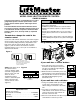
MODEL 33LM 3-BUTTON REMOTE CONTROL
OWNER’S MANUAL
Programming the opener
The green push button is recommended for use with a
garage door opener. The other push buttons can be
used to operate another opener and/or light control
product.
The 33LM 3-Button Remote Control Remote control
can also be used with a 423LM 3-channel receiver and
a 3-button door control to operate a commercial door
opener in open, close, and stop mode (as explained
on side 2).
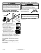
To match or change the code in the
remote control
Locate the code switches in both the new and the original
remote controls. The new remote control’s code switches
can be found by sliding the battery compartment cover
back. Place remote controls side by side as shown
(Figure 1) and set switches in all remote controls to
matching positions (+,0,–). Use a pen or screwdriver to
slide the code switches.
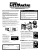
NOTE: Code switch #1 on
the 3-button remote
control is dormant, when
used with a single-button
remote control. Set code
switch #1, in the
single-button remote
control, to match the push
button selected on the
3-button remote control
(Figure 2).
+
0
–
1 2 3 4 5 6 7 8 9
+
0
–
1 2 3 4 5 6 7 8 9
Match code switches (2-9)
between old remote control and
new remote control (Code switch
#1 on the 3-button remote
control is dormant)
Push Buttons
(+) (–)
(0)
To prevent possible SERIOUS INJURY or DEATH from a
moving gate or garage door:
• ALWAYS keep remote controls out of reach of children.
NEVER permit children to operate, or play with remote
controls.
• Activate gate or door ONLY when it can be seen clearly, is
properly adjusted, and there are no obstructions to door
travel.
• ALWAYS keep gate or garage door in sight until completely
closed. NEVER permit anyone to cross path of moving gate
or door.
WARNING
CAUTION
WARNING
WARNING
ATTENTION
AVERTISSEMENT AVERTISSEMENT
AVERTISSEMENT
If your unit has a “Learn” button:
1. Press and release the “learn” button
located on the back panel of the motor
unit. The learn indicator light will glow
steadily for 30 seconds.
2. Within the 30 second window, press and
hold the button on the hand-held remote.
3. The unit will either activate or the opener
light bulb will blink signifying it has
learned the code.
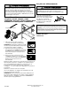
If your unit has code switches:
1. Using a step ladder climb up to the back
of your motor unit. Check the code
switch settings on the back of the motor
unit.
2. Use a pen or screw driver to set the
code switches on the back of the remote
control to match the code switches on
the back of the motor unit.
3. Once the code switches have been set push the remote
control button to activate your unit.
H
I
G
H
+
0
–
123 456789
+
0
—
123456789
H
I
G
H
N
O
R
Replacement Parts
Remote case housing
(circuit board not included) . . . . . . . . . . . . . .41A3580-4
Visor clip . . . . . . . . . . . . . . . . . . . . . . . . . . . . . . .29C128
12V battery . . . . . . . . . . . . . . . . . . . . . . . . . . . . . .10A14
Figure 1
Figure 2
1