
Instructions / Assembly


Ten-Foot Rail Extension Kit
Model 7710CB and 7710CB-P
The garage door MUST be in the fully closed position during
installation.
To prevent possible SERIOUS INJURY or DEATH:
• Disconnect ALL electric and battery power BEFORE performing
ANY service or maintenance.
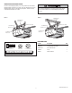
Figure 1
Figure 2
To remove rail pry both
end tabs of front
rail slightly outward
Idler Bolt hole
(KEEP LARGER
ONE ON TOP)
NEW
FRONT RAIL
CORRECT
INCORRECT
Rail Tab
Rail Tab
Threaded
Shaft
Outer
Nut
Front Rail
Section
(TO DOOR)
Inner
Nut
Lock
Washer
Master
Link
Master
Link
BEFORE YOU BEGIN:
• The trolley must be in down (closed door) position during assembly and
installation. If you have a completely installed garage door opener,the
rail/opener assembly must be taken down. UP and DOWN Limits must be
readjusted after installation.
• Opener hanging brackets will require repositioning and the addition of an
extra bracket for stability due to increased rail length.
IF THIS IS A NEW INSTALLATION:
Use the front (header), chain/cable assembly, and longer emergency release
rope in this kit in place of those packaged with your garage door opener.
Add the enclosed center rail as the second rail section, creating a five piece
rail assembly. Complete the assembly, installation, and adjustment of your
opener according to your owner’s manual, with the exception of adding an
additional hanging bracket for stability.
IF THIS IS AN EXISTING INSTALLATION, CONTINUE AS FOLLOWS:
1. Disconnect power to opener.
2. Pull down on the emergency release handle, then disconnect the
trolleyfrom the door arm.
3. Disconnect the rail/opener assembly from the header bracket and
hanging brackets, and place it on the floor.
4. Remove the outer nut (Figure 1) from the trolley shaft and set aside.
5. Disconnect the two master link assemblies from the trolley (Figure 1)
and discard.
6. Remove idler pulley assembly and set aside.
7. Remove the chain/cable assembly and discard.
8. Push the trolley back toward the opener. Disconnect the front rail and
second rail sections by using a screwdriver tip to pry up the outer tab
on each side of the rail (Figure 2), then slide it off the existing rail
assembly. Discard the front and second rails.
9. Align the new front and center rails with the existing rail assembly,
keeping the cut out “window” at the front (header) end. Be sure to keep
rails right side up: the idler pulley bolt hole above the window is larger
on top of the rail than on the bottom. Slide the new center rail onto the
assembly, then add the front rail. Tabs along the side will lock into
place.
10. As a temporary stop, insert a screwdriver into the hole 10" (25 cm)
from the front end of the rail (Figure 1). Slide the trolley assembly to
this point.
11. Locate the rail tab. Use a flathead screwdriver and lift the rail tab until
the tab is vertical (90°) (Figure 2).
12. Refer to your owner’s manual to complete the assembly, re-installation
and adjustment of your opener. NOTE: Before hanging the opener, an
additional hanging bracket is necessary for stability. See Adding An
Additional Hanging Bracket on reverse side. (Replace the old emergency
release rope with the new, longer replacement rope.)
13. Reconnect power.
14. Make adjustments and test the safety reversal system according to the
owner's manual.
WARNING: This product can expose you to chemicals including
lead, which are known to the State of California to cause cancer or
birth defects or other reproductive harm. For more information go to
www.P65Warnings.ca.gov