The Chamberlain Group, Inc. 845 Larch Avenue Elmhurst, Illinois 60126-1196 www.chamberlain.com ® ® GARAGE DOOR OPENER Model HD800D 1/2 HP For Residential Use Only Owner’s Manual ■ Please read this manual and the enclosed safety materials carefully! ■ Fasten the manual near the garage door after installation. ■ The door WILL NOT CLOSE unless The Protector System® is connected and properly aligned. ■ Periodic checks of the opener are required to ensure safe operation.
TABLE OF CONTENTS Introduction 2-7 Adjustment Safety symbol and signal word review ...............................2 Preparing your garage door................................................3 Tools needed.......................................................................3 Planning ..........................................................................4-5 Carton inventory..................................................................6 Hardware inventory...........................................
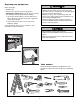
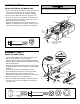
Preparing your garage door Before you begin: • Disable locks. • Remove any ropes connected to garage door. • Complete the following test to make sure your garage door is balanced and is not sticking or binding: 1. Lift the door about halfway as shown. Release the door. If balanced, it should stay in place, supported entirely by its springs. 2. Raise and lower the door to see if there is any binding or sticking. If your door binds, sticks, or is out of balance, call a trained door systems technician.
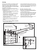
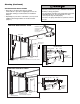
Planning Identify the type and height of your garage door. Survey your garage area to see if any of the conditions below apply to your installation. Additional materials may be required. You may find it helpful to refer back to this page and the accompanying illustrations as you proceed with the installation of your opener. Depending on your requirements, there are several installation steps which may call for materials or hardware not included in the carton.
Planning (Continued) ONE-PIECE DOOR INSTALLATIONS • Generally, a one-piece door does not require reinforcement. If your door is lightweight, refer to the information relating to sectional doors in Installation Step 11. • Depending on your door’s construction, you may need additional mounting hardware for the door bracket (Step 11). Without a properly working safety reversal system, persons (particularly small children) could be SERIOUSLY INJURED or KILLED by a closing garage door.
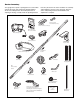
Carton Inventory Your garage door opener is packaged in one carton which contains the motor unit and all parts illustrated below. Accessories will depend on the model purchased. If anything is missing, carefully check the packing material. Parts may be stuck in the foam. Hardware for assembly and installation is shown on the next page. Save the carton and packing material until installation and adjustment is complete.
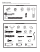
Hardware Inventory Separate all hardware and group as shown below for the assembly and installation procedures.
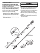
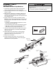
ASSEMBLY STEP 1 Assemble the Rail & Install the Trolley To prevent INJURY from pinching, keep hands and fingers away from the joints while assembling the rail. To avoid installation difficulties, do not run the garage door opener until instructed to do so. The front rail has a cut out “window” at the door end (see illustration). The hole above this window is larger on the top of the rail than on the bottom. A smaller hole 3-1/2" (8.9 cm) away is close to the rail edge.
ASSEMBLY STEP 2 Fasten the Rail to the Motor Unit To avoid SERIOUS damage to garage door opener, use ONLY those bolts/fasteners mounted in the top of the opener. • Insert a 1/4"-20x1-3/4" bolt into the cover protection bolt hole on the back end of the rail as shown. Tighten securely with a 1/4"-20 lock nut. Do NOT overtighten. • Remove the two bolts from the top of the motor unit. • Place the “U” bracket, flat side down, on the motor unit and align the bracket holes with the bolt holes.
ASSEMBLY STEP 4 Install the Belt and Attach the Belt Cap Retainer To avoid possible SERIOUS INJURY to fingers from moving garage door opener: • ALWAYS keep hand clear of sprocket while operating opener. • Securely attach sprocket cover BEFORE operating. 1. Pull the belt around the idler pulley and toward the trolley. The ribbed side must contact the pulley. 2. Hook the trolley connector into the retaining slot on the trolley as shown. 3.
ASSEMBLY STEP 5 Set the Tension • Insert a screwdriver tip into one of the nut ring slots and brace it firmly against the trolley. • Place a 7/16" open end wrench on the square end. Rotate the nut about 1/4 turn until the spring releases and snaps the nut ring against the trolley. This sets the spring to optimum belt tension. Nut Ring Slot Square End You have now finished assembling your garage door opener. Please read the following warnings before proceeding to the installation section.
INSTALLATION STEP 1 Unfinished Ceiling OPTIONAL CEILING MOUNT FOR HEADER BRACKET Determine the Header Bracket Location 2x4 Header Wall Vertical Centerline of Garage Door To prevent possible SERIOUS INJURY or DEATH: • Header bracket MUST be RIGIDLY fastened to structural support on header wall or ceiling, otherwise garage door might not reverse when required. DO NOT install header bracket over drywall. • Concrete anchors MUST be used if mounting header bracket or 2x4 into masonry.
INSTALLATION STEP 2 Wall Mount Install the Header Bracket You can attach the header bracket either to the wall above the garage door, or to the ceiling. Follow the instructions which will work best for your particular requirements. Do not install the header bracket over drywall. If installing into masonry, use concrete anchors (not provided).
INSTALLATION STEP 3 Attach the Rail to the Header Bracket NOTE: (Optional) With some existing installations, you may re-use the old header bracket with the two plastic spacers included in the hardware bag. Place the spacers inside the bracket on each side of the rail, as illustrated. • Position the opener on the garage floor below the header bracket. Use packing material as a protective base. NOTE: If the door spring is in the way you’ll need help.
INSTALLATION STEP 4 Position the Opener To prevent damage to garage door, rest garage door opener rail on 2x4 placed on top section of door. Follow instructions which apply to your door type as illustrated. SECTIONAL DOOR OR ONE-PIECE DOOR WITH TRACK A 2x4 laid flat is convenient for setting an ideal door-to-rail distance. • Remove foam packaging. • Raise the opener onto a stepladder. You will need help at this point if the ladder is not tall enough.
INSTALLATION STEP 5 Hang the Opener To avoid possible SERIOUS INJURY from a falling garage door opener, fasten it SECURELY to structural supports of the garage. Concrete anchors MUST be used if installing any brackets into masonry. Three representative installations are shown. Yours may be different. Hanging brackets should be angled, Figure 1, to provide rigid support. On finished ceilings, Figure 2, attach a sturdy metal bracket to structural supports before installing the opener.
INSTALLATION STEP 6 Install the Door Control To prevent possible SERIOUS INJURY or DEATH from electrocution: • Be sure power is not connected BEFORE installing door control. • Connect ONLY to 24 VOLT low voltage wires. To prevent possible SERIOUS INJURY or DEATH from a closing garage door: • Install door control within sight of garage door, out of reach of children at a minimum height of 5 feet (1.5 m), and away from ALL moving parts of door.
INSTALLATION STEP 7 Install the Lights To prevent possible OVERHEATING of the endpanel or light socket: • DO NOT use short neck or specialty light bulbs. • DO NOT use halogen bulbs. Use ONLY incandescent. To prevent damage to the opener: • DO NOT use bulbs larger than 100W. • ONLY use A19 size bulbs. • Press the release tabs on both sides of lens. Gently rotate lens back and downward until the lens hinge is in the fully open position. Do not remove the lens.
INSTALLATION STEP 9 Electrical Requirements To prevent possible SERIOUS INJURY or DEATH from electrocution or fire: • Be sure power is not connected to the opener, and disconnect power to circuit BEFORE removing cover to establish permanent wiring connection. • Garage door installation and wiring MUST be in compliance with ALL local electrical and building codes. • NEVER use an extension cord, 2-wire adapter, or change plug in any way to make it fit outlet. Be sure the opener is grounded.
INSTALLATION STEP 10 Install The Protector System® Be sure power is not connected to the garage door opener BEFORE installing the safety reversing sensor. To prevent SERIOUS INJURY or DEATH from a closing garage door: • Correctly connect and align the safety reversing sensor. This required safety device MUST NOT be disabled. • Install the safety reversing sensor so beam is NO HIGHER than 6" (15 cm) above garage floor.
INSTALLING THE BRACKETS Be sure power to the opener is disconnected. Install and align the brackets so the sensors will face each other across the garage door, with the beam no higher than 6" (15 cm) above the floor. They may be installed in one of three ways, as follows. Figure 1 DOOR TRACK MOUNT (RIGHT SIDE) Door Track Lip Indicator Light Garage door track installation (preferred): • Slip the curved arms over the rounded edge of each door track, with the curved arms facing the door.
MOUNTING AND WIRING THE SAFETY REVERSING SENSORS • Slide a 1/4"-20x1/2" carriage bolt head into the slot on each sensor. Use wing nuts to fasten sensors to brackets, with lenses pointing toward each other across the door. Be sure the lens is not obstructed by a bracket extension (Figure 5). • Finger tighten the wing nuts. • Run the wires from both sensors to the opener. Use insulated staples to secure wire to wall and ceiling. • Strip 7/16" (11 mm) of insulation from each set of wires.
INSTALLATION STEP 11 Fasten the Door Bracket Fiberglass, aluminum or lightweight steel garage doors WILL REQUIRE reinforcement BEFORE installation of door bracket. Contact your door manufacturer for reinforcement kit. Follow instructions which apply to your door type as illustrated below or on the following page. A horizontal reinforcement brace should be long enough to be secured to two or three vertical supports. A vertical reinforcement brace should cover the height of the top panel.
ONE-PIECE DOORS Please read and comply with the warnings and reinforcement instructions on the previous page. They apply to one-piece doors also. • Center the door bracket on the top of the door, in line with the header bracket as shown. Mark either the left and right, or the top and bottom holes. • Metal Doors: Drill 3/16" pilot holes and fasten the bracket with the 1/4"-14x5/8" self-threading screws provided.
INSTALLATION STEP 12 Pulley Connect Door Arm to Trolley 8" (20 cm) min. Follow instructions which apply to your door type as illustrated below and on the following page. Trolley Stop Bolt SECTIONAL DOORS ONLY • Make sure garage door is fully closed. Pull the emergency release handle to disconnect the outer trolley from the inner trolley. Slide the outer trolley back (away from the pulley) about 8" (20 cm) as shown in Figures 1, 2 and 3.
ALL ONE-PIECE DOORS Door Bracket 1. Assemble the Door Arm: • Fasten the straight and curved door arm sections together to the longest possible length (with a 2 or 3 hole overlap). • Make sure the garage door is fully closed. Connect the straight door arm section to the door bracket with the 5/16"x1-1/4" clevis pin. • Secure with a ring fastener.
ADJUSTMENT STEP 1 Program the Travel Limits Without a properly installed safety reversal system, persons (particularly small children) could be SERIOUSLY INJURED or KILLED by a closing garage door. • Incorrect adjustment of garage door travel limits will interfere with proper operation of safety reversal system. • After ANY adjustments are made, the safety reversal system MUST be tested. Door MUST reverse on contact with 1-1/2" high (3.8 cm) object (or 2x4 laid flat) on floor.
ADJUSTMENT STEP 2 Setting the Force Without a properly installed safety reversal system, persons (particularly small children) could be SERIOUSLY INJURED or KILLED by a closing garage door. • After ANY adjustments are made, the safety reversal system MUST be tested. Door MUST reverse on contact with 1-1/2" high (3.8 cm) object (or 2x4 laid flat) on floor. The force setting button is located on the back panel of the motor unit.
ADJUSTMENT STEP 3 Test the Safety Reversal System Without a properly installed safety reversal system, persons (particularly small children) could be SERIOUSLY INJURED or KILLED by a closing garage door. • Safety reversal system MUST be tested every month. • After ANY adjustments are made, the safety reversal system MUST be tested. Door MUST reverse on contact with 1-1/2" high (3.8 cm) object (or 2x4 laid flat) on the floor. TEST • With the door fully open, place a 1-1/2" (3.
WARNING OPERATION IMPORTANT SAFETY INSTRUCTIONS WARNING To reduce the risk of SEVERE INJURY or DEATH: 1. READ AND FOLLOW ALL WARNINGS AND INSTRUCTIONS. 2. ALWAYS keep remote controls out of reach of children. NEVER permit children to operate or play with garage door control push buttons or remote controls. 3. ONLY activate garage door when it can be seen clearly, it is properly adjusted and there are no obstructions to door travel. 4. ALWAYS keep garage door in sight until completely closed.
Using the Wall-Mounted Door Control Additional feature when used with the 3-Button handheld remote To control the opener lights: In addition to operating the door, you may program the remote to operate the lights. 1. With the door closed, press and hold a small remote button that you want to control the light. 2. Press and hold the Light button on the door control. 3. While holding the Light button, press and hold the Lock button on the door control. 4. After the opener lights flash, release all buttons.
BATTERY BACKUP UNIT Mounting the battery backup unit (BBU) can be done using one of two methods. The BBU can be mounted directly on top of the motor unit or it can be secured on a structural support just above it. To prevent possible SERIOUS INJURY or DEATH from electrocution, disconnect power to motor unit BEFORE proceeding. 2. Mounting the BBU Directly to the Ceiling Structural Support.
Battery Backup Unit (BBU) Diagnostics WARNING To reduce the risk of FIRE or INJURY to persons use only Chamberlain part #41B591 for replacement batteries. WARNING (Red LED) (Yellow LED) (Green LED) OPERATING INSTRUCTIONS 1. Test the installed BBU with the motor unit. To test the BBU, disconnect the motor unit power cord from the electrical outlet. • A solid yellow LED indicates the BBU is operating on battery power.
THE REMOTE CONTROL BATTERY CARE OF YOUR OPENER MAINTENANCE SCHEDULE To prevent possible SERIOUS INJURY or DEATH: • NEVER allow small children near batteries. • If battery is swallowed, immediately notify doctor. To reduce risk of fire, explosion or chemical burn: • Replace ONLY with 3V2032 coin batteries. • Do NOT recharge, disassemble, heat above 100°C (212°F) or incinerate. Once a Month • Manually operate door. If it is unbalanced or binding, call a trained door systems technician.
8. The door opens but won't close: • If the opener lights blink, check the safety reversing sensor. See Installation Step 10. • If the opener lights don’t blink and it is a new installation. See Adjustment Step 2. For an existing installation, see below. Repeat the safety reverse test after the adjustment is complete. HAVING A PROBLEM? 1. The opener doesn't operate from either the Door Control or the remote control: • Does the opener have electric power? Plug a lamp into the outlet.
Bell Wire Installed Safety Reversing Sensor Diagnostics Located On Motor Unit LED or Diagnostic LED “Learn” Button Safety Reversing Sensor Your garage door opener is programmed with self-diagnostic capabilities. The “Learn” button/diagnostic LED will flash a number of times then pause signifying it has found a potential issue. Consult Diagnostic Chart below. Diagnostic Chart 1 FLASH Safety Reversing Sensors wire open (broken or disconnected).
PROGRAMMING NOTICE: If this Security✚® garage door opener is operated with a non-rolling code transmitter, the technical measure in the receiver of the garage door opener, which provides security against code-theft devices, will be circumvented. The owner of the copyright in the garage door opener does not authorize the purchaser or supplier of the non-rolling code transmitter to circumvent that technical measure.
To Add, Reprogram or Change a Keyless Entry PIN NOTE: Your new Keyless Entry must be programmed to operate your garage door opener. USING THE “LEARN” BUTTON USING THE MOTION DETECTING CONTROL PANEL —— ——— ——— ——— ——— —— LOCK LIGHT NOTE: This method requires two people if the Keyless Entry is already mounted outside the garage. 1. Press and release the “learn” button on motor unit. The learn indicator light will glow steadily for 30 seconds. 1.
REPAIR PARTS Rail Assembly Parts 2 1 3 4 6 5 7 KEY NO. PART NO. 1 2 3 4 5 6 7 4A1008 41C5141-2 41A5665-2 41B4103 144C54 41A5250 12D598-1 183A163 DESCRIPTION Master link kit Complete trolley assembly Complete rail Spring trolley nut Idler pulley Full belt assembly “U” bracket NOT SHOWN Wear pads Installation Parts 4 2 KEY PART NO. NO.
Motor Unit Assembly Parts 1 13 2 3 12 4 9 8 7 5 6 11 10 KEY NO. PART NO. 1 2 3 4 41C76 41B4245 41B4375-2 41C5317 41C5839 41C5806 41C5418 41D605-1 41DB001 5 6 DESCRIPTION Belt cap and sprocket Line cord Terminal block w/screws Wire harness (logic) High voltage wire harness DC motor wire harness Light socket wire harness Motor 80kg/100kg Receiver logic board assembly with end panel KEY NO. PART NO.
ACCESSORIES 953D 3-Button SECURITY✚® Remote Control: Includes visor clip. 7702CB Outside Quick Release: Required for a garage with NO access door. 956D 3-Button Mini-Remote Control with SECURITY✚®: With key ring and fastening strip. 760CB Outdoor Key Switch: Operates the garage door automatically from outside when remote control is not handy. 940D SECURITY✚® Keyless Entry: Enables homeowner to operate garage door opener from outside by entering a password on a specially designed keyboard.
OPERATOR NOTES 42
OPERATOR NOTES 43
CHAMBERLAIN SERVICE IS ON CALL HOW TO ORDER REPAIR PARTS OUR LARGE SERVICE ORGANIZATION SPANS AMERICA Selling prices will be furnished on request, or parts will be shipped at prevailing prices and you will be billed accordingly. INSTALLATION AND SERVICE INFORMATION IS AS NEAR AS YOUR TELEPHONE. SIMPLY DIAL OUR TOLL FREE NUMBER: WHEN ORDERING REPAIR PARTS, ALWAYS GIVE THE FOLLOWING INFORMATION: • PART NUMBER • PART NAME • MODEL NUMBER 1-800-528-9131 ADDRESS ORDERS TO: THE CHAMBERLAIN GROUP, INC.