OWNER'S MANUAL MODEL SL920 COMMERCIAL SLIDE GATE OPERATOR SL920 GATE OPERATORS ARE FOR USE ON VEHICULAR PASSAGES ONLY AND NOT INTENDED FOR USE ON PEDESTRIAN PASSAGE GATES.
Contents Pg. General Information.................................................................................................................3, 4 Features...................................................................................................................................5 Parts Identification...................................................................................................................6, 7 Installation....................................................................
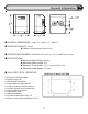
General Information OVERALL DIMENSIONS: Height: 21" Length: 12" Width: 17" SHIPPING WEIGHT: 125 lbs. z Options: Steel Mounting Stand: 23 lbs. POWER REQUIREMENT: Dedicated 115 Volt AC (+/- 10V), 5 AMP Power Circuit APPLICATIONS: z Maximum Gate Weight: 500 lbs. z Maximum Gate Length: 25 ft. z Maximum Track Grade: 5 % (1 ft. rise over 20 ft. run) z Maximum Gate Speed: 10"/sec.
General Information continued... CIRCUIT BOARD: The SL920 uses the Full Systems Capability circuit board, a powerful control system. This circuit board operates on 12 ~ 18 Volts and can deliver power to the motor through high power switching. The limit switch input terminals require the use of normally open type limit switches. These switches are used to accurately stop the gate operator in the open and closed positions.
Features OPERATION The SL920 Full Systems Capability can operate in a AUTO CLOSE TIMER (TIMER ON) or a PUSH-TO-OPEN/PUSH-TO-CLOSE (TIMER OFF) mode of operation. In the AUTO CLOSE TIMER mode of operation the operator is given a command to open the gate and hold it open until the input is released and until the auto close timer has elapsed at which point the operator will close the gate automatically.
Parts Identification 6
Parts Identification continued... K72-30359 SERVICE KIT LIMIT/DRIVE SHAFT ASSEMBLY DESCRIPTION K74-40065 A SERVICE KIT F EXTERNAL RESISTOR DESCRIPTION QTY QTY LIMIT/DRIVE SHAFT 1 EXTERNAL CURRENT RESISTOR BEARING 2 SHRINK WRAP, 1" 2 LIMIT NUT 2 SCREW, PH PHILLIPS, #2-56 X 1/2" 2 SPROCKET, 41B20, 1/4" KW, (2) 1/4" SS 1 LOCKNUT, #2-56 2 KEY, WOODRUFF, 1/4" X 7/8" 1 WIRE, GREEN, 8", STIP X FORK 1 Steel shim washer, 1" x 1.5" x 0.
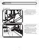
Installation TEST OPERATOR Remove the gate operator from it's package and make sure that all parts are included. Refer to General Information and Parts Identification. If any parts appear to be missing, contact dealer. Temporarily plug the operator into 115 Volt outlet or extension cord. 1 2 Before beginning installation, test the gate operator by running the operator back and fourth 2 or 3 times. If the gate operator appears to have any shipping damage, contact a dealer.
Installation continued... GATE PREPERATION 3 Disconnect Power from the gate operator! The tail end of the gate should extend approximately 24" beyond the edge of the driveway. If this is not the case, an extension tail will need to be added to the gate. This will give room for the gate operator. Make the extension tail 24" X 24" as shown. If the gate has not yet been fabricated, add 24" to the length of the gate.
Installation Continued... POSITION GATE OPERATOR 6 If the steel mounting stand was used, simply bolt the gate operator to the stand. If the operator will be mounted to a concrete surface or pad, place the shortest edge of the operator 4" away from the edge of the driveway. Place the longer edge of the gate operator 2-1/2" away from the gate.
Installation Continued... ATTACH CHAIN TO GATE 9 Attach the gate bracket to the gate as shown using the round or square u-bolts for round or square gate frames respectively. Attach the chain to the gate brackets using the chain bolt and master link as shown. If necessary, the chain may be easily shortened using a chain breaker. Adjust the height of the gate brackets until the chain is level and firmly tighten the u-bolts.
Alternate Installations REAR MOUNT PLACEMENT The rear mount installation is an excellent way to conceal the chain or operator. The operator is placed in the extreme rear of the gate as shown and the chain never goes across the driveway. The chain only goes from the gate operator to a post or wall beside the driveway. Place shortest edge of the operator 3" from the rear end of the gate and place the long edge of the operator 3-1/2" away from the gate toward the wall.
Electrical CONDUIT ROUTING Make sure that power is OFF before making any electrical connections! Be sure that all wiring is employed as required by local codes. The operator is provided with two knockout holes on each side. Run 1/2" liquid tight flexible conduit through one of the four knockout holes and into the handy box where the receptacle is located. An elbow fitting is attached to the handy box and a straight fitting is supplied for the other end of the flexible conduit.
Electrical Continued... BATTERY BACK-UP If the gate operator is already factory equipped with battery run, only the Right/Left Side switch and the Mode switch need to be set. The Right/Left switch simply needs to be set in the same position as the Right/Left switch on the main control board. (See page 17 for correctly setting the Right/Left switch on the control board) The Mode switch can be set in either the Mode 1 or Mode 2 position.
Electrical Continued... 1 2 3 412 HM RADIO RECEIVER 4 GRY GRY 24 25 SWITCH2 OFFON OPEN ADJUST ORG INCREASE SENSITIVITY ADJUSTMENTS 4 ! CLOSE ADJUST SAFETY 5 PULSE OPEN 7 8 N.C. - 9 N.C. STOP CLOSE N.O. 10 N.O. N.O. STOP 11 12 + REMOVE JUMPER IF USING N.C. STOP SAFETY NOTES: Controls must be far enough from the gate so that the user is prevented from coming in contact with the gate while operating the controls.
Wiring Diagrams, Button Controls z One button, two button and three button controls may be connected individually or together as shown below. Most button controls have a common "buss bar" which connects the common terminals of all buttons together so that only one common wire needs to be run back to the gate operator control board. If this is not the case, the common terminals of each button may be connected together with wire.
Fine Tuning ADJUST TIMER The gate operator is designed to work differently while opening then while closing to optimize safety, so the direction of the operator will need to be set. Setting the operator direction is done by flipping the right/ left side switch located at the top of the circuit board. For a left side installation flip the switch to the left and for a right side installation, flip the switch to the right (see illustration above).
Master/Second Wiring SL920 MASTER/SECOND z Connect 115 Volts AC to each SL920 gate operator. Connect the four Master/Second wires from the master circuit board to the Second circuit board as shown below. Any operator can be used as either a master or a Second. Accessories can be connected to the master or second operator. z Switch the Auto Close Timer switch to the OFF position on the Second circuit board.
Wiring Diagram SL920 WITH FULL SYSTEMS CAPABILITY 19
Wiring Diagrams SL920 WITH BATTERY BACK-UP BREAKER 15 AMP 20
Safety Edge and Warning Placard Installation See reversing edge sensor instructions for the exact placement of the reversing edge contact sensors. One or more safety edge contact sensors shall be located at the leading edge, trailing edge, and post mounted both inside and outside of a vehicular horizontal slide gate. When the contact sensor is hard wired, it shall be located and its wiring arranged so that the communication between the sensor and the gate operator is not subjected to mechanical damage.
Options If it is desired that the driveway illuminate when the gate is activated, a light delay timer may be installed. The light delay timer will switch power on to the light for two minutes, then shut power back off. The timer relay is capable of switching up to 10 Amps which will handle most flood or spot lights available. A general hook-up diagram for the light and timer is shown at left. 1 The standard auto close timer built into the circuit board can be adjusted to between 0 and 45 seconds.
Options 4 For rear mount installation that are limited on space for the gate to slide back into, the space saver version is an excellent alternative. There may be a property wall, parking stall or other obstacle that reduces the amount of space available, making it difficult to mount the gate operator and still have room for the gate to slide. The space saver version of the gate operator places the drive shaft externally so that the gate can slide past the gate operator, picking up allot of extra space.
Options Continued...
Maintenance and Safety The SL920 is designed to be MAINTENANCE FREE. However, for optimum performance and safety, the following maintenance procedures should be taken. Gate Sensitivity Adjustments The most important thing to maintain on any gate is the safety equipment. As the gate becomes older the amount of force necessary to move the gate will vary. When this happens, the gate sensitivity adjustments may need to be readjusted.
Troubleshooting EXPLANATION OF VISUAL FEEDBACK LEDs The SL920 Full Systems Capability circuit board has been equipped with Visual Feedback LEDs to simplify installation and troubleshooting. These are small lights which are located directly beside the input terminals. These LEDs give visual information to the installer or service technician indicating what commands are going into the circuit board from devices such as limit switches or from peripheral devices such as radio receivers or safety loops.
Troubleshooting GATE WILL NOT OPEN OR CLOSE Test the operator to find out whether the open input devices are functioning by following these steps. n If a remote control is being used to open the gate, try another remote control or try using a push button if there is one installed. o If a push button is being used try using another push button or a remote control.
Notes Other Commonly Used Open and Safety Devices Be sure to read this entire manual before attempting to perform any type of installation or service to the gate opener. Once the installation has been completed, this installation and service manual becomes the property of the home owner or end user and should be given to the new owner at that time. For a personal copy of this manual, please contact a LiftMaster. NOTE: z All open and safety devices must have normally open contacts.
Notes Be sure to read this entire manual before attempting to perform any type of installation or service to the gate opener. Once the installation has been completed, this installation and service manual becomes the property of the home owner or end user and should be given to the new owner at that time. For a personal copy of this manual, please contact an LiftMaster distributor.
Notes 30
Notes 31
HOW TO ORDER REPAIR PARTS OUR LARGE SERVICE ORGANIZATION SPANS AMERICA INSTALLATION AND SERVICE INFORMATION ARE AVAILABLE 6 DAYS A WEEK CALL OUR TOLL FREE NUMBER - 1-800-528-2806 MONDAY Through FRIDAY 5:00 a.m. TO 6:00 p.m. (MST) SATURDAY 7:00 a.m. TO 3:30 p.m. (MST) WWW.LIFTMASTER.COM WHEN ORDERING REPAIR PARTS PLEASE SUPPLY THE FOLLOWING INFORMATION: PART NUMBER DESCRIPTION MODEL NUMBER ADDRESS ORDER TO: THE CHAMBERLAIN GROUP, INC.