The Chamberlain Group, Inc. 845 Larch Avenue Elmhurst, Illinois 60126-1196 www.liftmaster.com MADCBB, MATDCBB, MASDCBB, & MASTDCBB HEAVY-DUTY DC BARRIER GATE OPERATOR OWNER'S MANUAL RADIO RECEIVEEDR INCLUD MEGA ARM TOWER & MEGA SPRINT TOWER MEGA ARM & MEGA SPRINT IMPORTANT: Read and understand Warranty Page first. Batteries (included) MUST be connected for proper operation of operator. Use (2) LiftMaster 12 Vdc 7AH (Part # MBAT).
TABLE OF CONTENTS SAFETY 2-4 OPERATION AND MAINTENANCE Safety Symbol and Signal Word Review UL325 Model Classifications Safety Installation Information 2 3 4 INTRODUCTION 5 Features Tools Needed Operator Specifications 5 5 5 INSTALLATION 6-7 Install the Concrete Pad and Conduit Attach the Operator to the Concrete Pad Install the Barrier Arm WIRING Power Wiring Input Commands Connections Accessory and Relay Connections Battery Installation Primary/Second Wiring INSTALL THE RECEIVER FEATURES AND F
SAFETY » UL325 MODEL CLASSIFICATIONS UL325 MODEL CLASSIFICATIONS I CLASS I – RESIDENTIAL VEHICULAR GATE OPERATOR A vehicular gate operator (or system) intended for use in a home of one-to four single family dwellings, or a garage or parking area associated therewith.
SAFETY » SAFETY INSTALLATION INFORMATION 1. Vehicular gate systems provide convenience and security. Gate systems are comprised of many component parts. The gate operator is only one component. Each gate system is specifically designed for an individual application. 2. Gate operating system designers, installers and users must take into account the possible hazards associated with each individual application.
INTRODUCTION » FEATURES + TOOLS NEEDED + OPERATOR SPECIFICATIONS FEATURES • Full service controller with eight inputs and LED indicators for loops, card reader, radio, etc. • Reversible arm direction for right or left handed operation. • Instant Reverse Device (IRD) monitor senses obstructions during motion. • Fail safe (auto open on AC power failure). • Raise gate input memory will memorize multiple vehicles – ideal for bar code scanners and AVI.
INSTALLATION » INSTALL THE CONCRETE PAD AND CONDUIT INSTALL THE CONCRETE PAD AND CONDUIT 24" Check the national and local building codes before installation. Layout the concrete pad for the operator. The concrete pad should be approximately 24" x 24" x 24" in order to ensure proper and stable operation. The pad should be 6" above the finished grade or even with top of curb (if applicable). NOTE: Pad should always extend below frost line in regions where ground will freeze. 6" 1 18" the conduit.
INSTALLATION » ATTACH THE OPERATOR TO THE CONCRETE PAD ATTACH THE OPERATOR TO THE CONCRETE PAD the operator on the concrete pad and mark the mounting 1 Position holes. 1/2" x 6" wedge anchors in the location of the mounting 2 Install holes. The wedge anchors should be installed with approximately 1-1/4" showing above the concrete pad in order to allow for the 1/2" thick base plate as well as washers for leveling. 3 Attach the operator to the concrete pad with appropriate fasteners.
WIRING » POWER WIRING To reduce the risk of SEVERE INJURY or DEATH: • ANY maintenance to the operator or in the area near the operator MUST NOT be performed until disconnecting the electrical power and locking-out the power via the operator power switch. Upon completion of maintenance the area MUST be cleared and secured, at that time the operator may be returned to service. • Disconnect power at the fuse box BEFORE proceeding.
WIRING » INPUTS INPUTS (J5 TERMINAL STRIP) DO NOT connect ANY device which would deliver ANY voltage of ANY kind to these terminals. The J5 terminal strip is used for controlling the barrier arm with various accessories such as receivers, loop detectors, access controls, and push button stations. Use common and normally open contacts from devices connected to these inputs. The J5 terminal strip is located on the top of the control board. Make connections to the appropriate points for the desired operation.
WIRING » ACCESSORY AND RELAY CONNECTIONS + BATTERY INSTALLATION ACCESSORY AND RELAY CONNECTIONS K1 These terminals will provide battery backed power to 24 Vdc devices and are located at the bottom of the control board at J4 terminals 1 and 2. Terminal 1 is 24 Vdc (+) and number 2 is 0 Vdc (-). Peripheral CLASS 2 low voltage devices that require 24 Vdc power maybe connected here (500 ma. maximum). EXAMPLE: Vehicle detector, radio receiver.
WIRING » PRIMARY/SECOND WIRING FIGURE 1 PRIMARY/SECOND WIRING In a primary/second configuration, either operator can be the primary. Choose an operator to be the primary and then direct all control wiring to it (also install vehicle detectors and receivers in it). At the primary, any input (at J5) with control wires (detectors, receivers, keypads, timers, etc.) to it must also be run to the same terminals of the second.
INSTALL THE RECEIVER » INSTALL THE RECEIVER To prevent possible SERIOUS INJURY or DEATH from a moving gate or garage door: • ALWAYS keep remote controls out of reach of children. NEVER permit children to operate, or play with remote control transmitters. • Activate gate or door ONLY when it can be seen clearly, is properly adjusted, and there are no obstructions to door travel. • ALWAYS keep gate or garage door in sight until completely closed. NEVER permit anyone to cross path of moving gate or door.
FEATURES AND FUNCTIONS » S1 DIP SWITCHES S1 DIP SWITCHES A S1 Dip Switch Block B C D E D 1 1 AUX LIMITS M/S D8 S1 R D1Ø 1 2 3 4 5 6 7 R1 8 S2 1 2 3 4 5 6 7 DIP Switch S1-7 The J4 Motor Wiring is controlled by DIP switch S1-7. The Handing of the Barrier Arm may be changed from right-hand to left-hand operation by reversing the factory default motor connections.
FEATURES AND FUNCTIONS » S2 DIP SWITCHES S2 DIP SWITCHES F S2 Dip Switch Block 1 G G H I 1 AUX LIMITS M/S D8 S1 R D1Ø 1 2 3 4 5 6 7 R1 8 S2 1 2 3 4 5 6 7 8 R12 H TIMER-TO-CLOSE DIP Switch S2-1 to S2-5 The S2-1 to S2-5 DIP switches will set the period of time the gate remains opened after reaching the OPEN position. Each DIP switch represents the number of seconds the gate will remain OPEN before CLOSING.
ADJUSTMENTS » INSTANT REVERSE DEVICE (IRD) + INSTALL THE BARRIER ARM To reduce the risk of SERIOUS INJURY or DEATH: • Disconnect power BEFORE performing ANY adjustments near drive shaft.
OPERATION AND MAINTENANCE » GENERAL SERVICE + SHEAR PIN REPLACEMENT + BATTERY To avoid SERIOUS PERSONAL INJURY or DEATH from electrocution, disconnect ALL electric power BEFORE performing ANY maintenance. Check at the intervals listed in the following chart: ITEM PROCEDURE Fasteners Check and tighten as required Bearings and Shafts Check for wear and lubricate Battery Maintenance Replace batteries.
ADDITIONAL FEATURES » SUGGESTED LOOP SENSOR LOCATIONS SUGGESTED LOOP SENSOR LOCATIONS Do not allow control devices to be within 10 feet of gate or operator. RECOMMENDATIONS: • If vehicle detectors are used to open or close the gate, use of the presence contacts are recommended. Using the pulse contacts will REDUCE the gate’s safe operation. • If closing timer is to be used, use ONLY on a dedicated free exit. • Close loop must be centered under gate arm.
ADDITIONAL FEATURES » TRAP INSTRUCTIONS TRAP INSTRUCTIONS INSTALL THE K1 AUXILIARY RELAY AND CONNECTOR AT MEGA ARM CONNECTED TO THE ACCESS DEVICE RECONNECT THE POWER AND TEST 1. Reconnect the DC power by replacing the neutral (Black) wire to the battery terminal. 2. Reconnect the AC Power to the operator. 3. To test, activate the following sequence of inputs: • Open the trap gate using the access device. • When the trap gate is open, activate the close loop on the trap operator.
ADDITIONAL FEATURES » SEQUENCE ACCESS MANAGEMENT SYSTEM (SAMS) WITH "MEMORY" SEQUENCE ACCESS MANAGEMENT SYSTEM (SAMS) WITH "MEMORY" NOTE: Insert a jumper across the JP2 terminal to allow the SAMS feature to work with the multiple vehicle memory count selection, use the K1 relay to open the sequenced gate (S1-5 off, S2-6 on, jumper across JP2). This allows gate to store input counts via J5 #4 but not raise the arm until the sequenced slide or swing gate has fully opened.
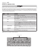
ADDITIONAL FEATURES » CONTROL BOARD LAYOUT + INPUT LOCATIONS CONTROL BOARD LAYOUT Open Gate Inputs - Reader, Push Button Aux Open / Reset (Pulse Open/Close) Safety Loop Input Close Gate Input - Close Loop Back Away - Free Exit Loop Shadow Loop Commons - 0 Vdc 7 8 CLOSE R21 R16 OPEN 1 OPEN 2 OPEN 3 R24 C3 R23 OLS D7 R22 OPEN R49 R6Ø R33 R39 R44 R48 R43 R59 R43 R63 D21 IRD1 R25 U5 U7 DX3 X2 CLOSE D4 R7 U1Ø DX4 R57 CLS D3 C13 R56 R6 IRD D2 C4 U3 R5 CPU D9 1A DC R2Ø C5 C2Ø
TROUBLESHOOTING » BATTERY CHECKOUT + GATE NOT OPERATING WARNING - DISCONNECT BATTERIES AND AC POWER BEFORE SERVICING ANY MECHANICAL OR MOVING COMPONENTS. BATTERY CHECKOUT When the batteries become weak the gate will begin to run noticeably slower. NOTE: Batteries should only be checked when you are sure they have had adequate time to fully charge. 1. Turn off the AC power and run gate for 5 to 10 cycles while observing low battery indicator LED D12.
REPAIR PARTS » PART NUMBERS AND DESCRIPTIONS + PARTS SHIPPED + MEGA ARM TOWER UNIQUE PARTS LIST + MEGA ARM OPTIONS PARTS LIST 20 13 10 21 12 5 18 11 2 16 1 8 18 9 7 17 19 15 3 14 4 NOTE: Mega Arm Tower not shown 6 PART NUMBERS AND DESCRIPTIONS ITEM 1 2 3 4 5 6 7 8 9 10 11 12 13 PART NUMBER MA001 MA002 MA003 MBAT MA005 MA006 MA007 MA008 MA009 MA010 MA011 MA012 MA013 ITEM 14 15 16 DESCRIPTION Controller Removable Connector DC Motor - 24 Vdc 12 Vdc 7AH Battery 2 required Gear Reducer 60:1 Alu
ACCESSORIES REMOTE CONTROLS NYLON ARM NUTS (Pkg. of 50). Model MA021 Chamberlain offers a variety of LiftMaster Security✚® and Passport ™ remote controls to satisfy your application needs. Single-button to 4-button, visor or key chain. Additionally, Passport ™ remote controls are ideal for integration with Telephone Entry and Access Control Systems. Contact your authorized LiftMaster dealer for details. NYLON ARM NUTS (Pkg. of 50), thin. Model MA021A ADAPTER COLLARS For padded arm option (2 included).
WARRANTY POLICY (YOU MUST READ, UNDERSTAND AND AGREE WITH ALL ITEMS IN THE LIMITED WARRANTY) LiftMaster warrants the MEGA ARM-UL to be free of defects in workmanship and materials for a period of 2 years for electronics and mechanical components and includes a 10 year corrosion perforation warranty on the cover and chassis. Warranty will begin from the date of purchase. LiftMaster reserves the right of final determination as to the existence and causes of any defect or failure.