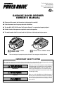
The Chamberlain Group, Inc. 845 Larch Avenue Elmhurst, Illinois 60126-1196 www.chamberlain.com GARAGE DOOR OPENER OWNER’S MANUAL ■ Please read this manual and the enclosed safety materials carefully! ■ Fasten the manual near the garage door after installation. ■ The door WILL NOT CLOSE unless The Protector System® is connected and properly aligned. ■ Periodic checks of the opener are required to ensure safe operation.
TABLE OF CONTENTS Preparing Your Garage Door . . . . . . . . . . . . . . . . . . .2 Having a Problem?. . . . . . . . . . . . . . . . . . . . . . . . .26 Completed Installation . . . . . . . . . . . . . . . . . . . . . . .3 Diagnostic Chart . . . . . . . . . . . . . . . . . . . . . . . . . .27 Tools Needed . . . . . . . . . . . . . . . . . . . . . . . . . . . . .4 Programming Opener Contents . . . . . . . . . . . . . . . . . . . . . . . . . . .
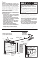
Planning Identify the type and height of your garage door. If you have a one-piece door, follow the assembly instructions contained in this manual and refer to the Installation Instructions One-Piece Door for installation procedures. Survey your garage area to see if any of the conditions below apply to your installation. Additional materials may be required. You may find it helpful to refer back to this page and the accompanying illustrations as you proceed with the installation of your opener.
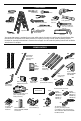
TOOLS NEEDED Drill 1/4" Nutdriver 2 X 4 Board Wire Cutters Pliers Drill Bits 3/16", 5/16" and 5/32" Adjustable End Wrench Tape Measure Carpenter’s Level (Optional) Sockets and Wrench 1/2", 5/8", 7/16", 9/16" and 1/4" Phillips and Flat Screwdriver Stepladder Claw Hammer Pencil Hack Saw Your garage door opener is packaged in one carton which contains the motor unit and the parts illustrated below. Note that accessories will depend on the model purchased.
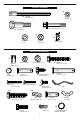
ASSEMBLY HARDWARE B7 B1 B5 Threaded Trolley Shaft (1) Nut 3/8" (1) B6 Idler Bolt (1) Bolt 1/4"-20 x 1-3/4" (2) B3 B2 B4 Lock Nut 1/4"-20 (2) Lock Washer 3/8" (1) Master Link (2) INSTALLATION HARDWARE C1 C3 C2 Nut 5/16"-18 (4) Insulated Staples (30) C6 Lag Screw 5/16"-18 x 1-7/8" (2) Lock Washer 5/16" (7) C9 C5 C4 Ring Fastener (3) Clevis Pin 5/16" x 1-1/4" (1) C10 Screw 6AB x 1-1/4" (2) Clevis Pin 5/16" x 1-1/2" (1) C8 Self-Threading Screw 1/4"-14 x 5/8" (2) C11 Screw 6-32 x 1" (2)
ASSEMBLY To prevent INJURY from pinching, keep hands and fingers away from the joints while assembling the rail. Assemble the Rail IMPORTANT NOTE: Remove the straight door arm and hanging brackets packaged inside the front rail 1 As a temporary trolley stop, insert a screwdriver into the hole 10" (25 cm) away from the front of the rail, as shown.
To avoid SERIOUS damage to opener, ONLY use bolts/fasteners mounted in top of motor unit.
Route Chain/Cable Around Rail Assembly and Motor Unit Sprocket To avoid possible SERIOUS INJURY to fingers: • Securely attach chain spreader. • NEVER connect garage door opener to power source until instructed to do so.
INSTALLATION IMPORTANT INSTALLATION INSTRUCTIONS WARNING To reduce the risk of SEVERE INJURY or DEATH: 7. NEVER connect garage door opener to power source until instructed to do so. 8. NEVER wear watches, rings or loose clothing while installing or servicing opener. They could be caught in garage door or opener mechanisms. 9. Install wall-mounted garage door control: • within sight of the garage door • out of reach of children at minimum height of 5 feet (1.5 m) • away from ALL moving parts of the door.
INSTALLATION To prevent possible SERIOUS INJURY or DEATH: • Header bracket MUST be RIGIDLY fastened to structural support on header wall or ceiling, otherwise garage door might NOT reverse when required. • NEVER try to loosen, move or adjust garage door, springs, cables, pulleys, brackets, or their hardware, ALL of which are under EXTREME tension. INSTALL THE HEADER BRACKET NOTE: You can fasten the header bracket within 4 feet (1.
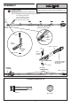
MOUNT THE HEADER BRACKET 4 Horizontal Line Highest Point of Travel 5 Mark Bracket Holes Center bracket on the “center of garage door” line and the horizontal line made in Step 2. A14 Bracket Mark the top and bottom bracket holes 6 Drill Holes Attach Bracket Secure bracket with lag screws Drill two 3/16" pilot holes C16 Lag Screw Center of Garage Door Ceiling Mount the Header Bracket (Optional) NOTE: If your installation requires that the header bracket be mounted to the ceiling.
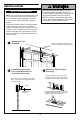
POSITION AND HANG MOTOR UNIT 1 To avoid possible SERIOUS INJURY from a falling garage door opener, fasten it SECURELY to structural supports of the garage. Open Door to Full Open Position and Rest Rail on a 2x4 to Position Opener at the Proper Angle for Hanging from the Ceiling To prevent damage to garage door, rest garage door opener rail on 2x4 placed on top section of door.
To prevent damage to garage door, reinforce inside of door with angle iron both vertically and horizontally. HORIZONTAL AND VERTICAL REINFORCEMENT Horizontal and vertical reinforcement (not provided) is needed for light weight garage doors (fiberglass, aluminum, steel, doors with glass panel, etc.). Top of Door A horizontal reinforcement brace should be long enough to be secured to two or three vertical supports. A vertical reinforcement brace should cover the height of the top panel.
ATTACH DOOR ARM TO TROLLEY To prevent possible SERIOUS INJURY or DEATH from a falling garage door: • If possible, use emergency release handle to disengage trolley ONLY when garage door is CLOSED. Weak or broken springs or unbalanced door could result in an open door falling rapidly and/or unexpectedly. • NEVER use emergency release handle unless garage doorway is clear of persons and obstructions. • NEVER use handle to pull door open or closed. If rope knot becomes untied, you could fall.
INSTALLING THE DOOR CONTROL 1 Strip Door Control Wire 2 To prevent possible SERIOUS INJURY or DEATH from electrocution: • Be sure power is NOT connected BEFORE installing Door Control. • Connect ONLY to 24 VOLT low voltage circuit. To prevent possible SERIOUS INJURY or DEATH from a closing garage door: • Install Door Control within sight of garage door, out of reach of children at a minimum height of 5 feet (1.5 m), and away from ALL moving parts of door.
INSTALLING THE LIGHT BULB(S) 1 To prevent possible OVERHEATING of the endpanel or light socket: • DO NOT use short neck or specialty light bulbs. • DO NOT use halogen bulbs. Use ONLY incandescent. To prevent damage to the opener: • DO NOT use bulbs larger than 100W. • ONLY use A19 size bulbs.
INSTALL THE PROTECTOR SYSTEM® To prevent SERIOUS INJURY or DEATH from a closing garage door: • Correctly connect and align the safety reversing sensor. This required safety device MUST NOT be disabled. • Install the safety reversing sensor so beam is NO HIGHER than 6" (15 cm) above garage floor. The safety reversing sensor must be connected and aligned correctly before the garage door opener will move in the down direction. NOTE: DO NOT operate the opener at this time.
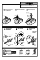
INSTALL THE PROTECTOR SYSTEM® 1 2 Assemble Safety Reversing Sensors Mount Brackets Garage door track installation (preferred) A17 Safety Reversing Sensor Door Track A17 Safety Reversing Sensor Indicator Lens Light C12 Carriage Bolts Sensor Beam No Higher Than 6" (15 cm) Above Floor A10 Safety Sensor Bracket C14 Wing Nut Mount Brackets: Mounting Options 2a Floor installation (optional) 2b Wall installation (optional) 2c Wall installation with Extension Brackets (optional) Attach with concrete
WIRE SAFETY REVERSING SENSOR Option A: Installation Without Pre-Wiring 3.1a Run Safety Reversing Sensor Wire to Motor Unit 3.2a Separate the Black/White and the White Wires and Secure with Insulated Staples PRE-WIRED INSTALLATIONS: If your garage already has wires installed for the safety reversing sensors, refer to the instructions on the following page. Strip 7/16" (11 mm) C1 Insulated Staple 7/16" (11 mm) Strip 7/16 inch (11 mm) of insulation from each set of wires. Separate the wires.
WIRE SAFETY REVERSING SENSOR Option B: Installation With Pre-Wiring 3.1b Cut Safety Reversing Sensor Wires 3.2b Strip Safety Reversing Sensor Wires and Pre-Installed Wires Cut the end of the safety sensor wire, making sure there is enough wire to reach the pre-installed wires from the wall. Separate the safety sensor wires and strip 7/16 inch (11 mm) of insulation from each end. Choose two of the pre-installed wires and strip 7/16 inch (11 mm) of insulation from each end.
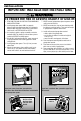
ADJUSTMENT Without a properly installed safety reversal system, persons (particularly small children) could be SERIOUSLY INJURED or KILLED by a closing garage door. • Incorrect adjustment of garage door travel limits will interfere with proper operation of safety reversal system. • If one control (force or travel limits) is adjusted, the other control may also need adjustment. • After ANY adjustments are made, the safety reversal system MUST be tested. Door MUST reverse on contact with 1-1/2" (3.
Without a properly installed safety reversal system, persons (particularly small children) could be SERIOUSLY INJURED or KILLED by a closing garage door. • Too much force on garage door will interfere with proper operation of safety reversal system. • NEVER increase force beyond minimum amount required to close garage door. • NEVER use force adjustments to compensate for a binding or sticking garage door. • If one control (force or travel limits) is adjusted, the other control may also need adjustment.
Without a properly installed safety reversal system, persons (particularly small children) could be SERIOUSLY INJURED or KILLED by a closing garage door. • Safety reversal system MUST be tested every month. • If one control (force or travel limits) is adjusted, the other control may also need adjustment. • After ANY adjustments are made, the safety reversal system MUST be tested. Door MUST reverse on contact with 1-1/2" (3.8 cm) high object (or 2x4 laid flat) on the floor.
OPERATION IMPORTANT SAFETY INSTRUCTIONS WARNING To reduce the risk of SEVERE INJURY or DEATH: 9. If one control (force or travel limits) is adjusted, the other control may also need adjustment. 10. After ANY adjustments are made, the safety reversal system MUST be tested. 11. Safety reversal system MUST be tested every month. Garage door MUST reverse on contact with 1-1/2" (3.8 cm) high object (or a 2x4 laid flat) on the floor.
USING THE WALL-MOUNTED DOOR CONTROL The Multi-Function Door Control Press the push bar/push button to open or close the door. Press again to reverse the door during the closing cycle or to stop the door while it’s opening. CARE OF YOUR OPENER Limit and Force Adjustments Push Bar Weather conditions may cause some minor changes in door operation requiring some readjustments, particularly during the first year of operation.
HAVING A PROBLEM? Bell Wire Sending Eye Safety Reversing Sensor (Amber Indicator Light) Safety Reversing Sensor “Learn” Button LED or Diagnostic LED 1. My door will not close and the light bulbs blink on my motor unit: The safety reversing sensor must be connected and aligned correctly before the garage door opener will move in the down direction. • Verify the safety reversing sensors are properly installed, aligned and free of any obstructions. Refer to Install The Protector System®.
DIAGNOSTIC CHART Your garage door opener is programmed with self-diagnostic capabilities. The “Learn” button/diagnostic LED will flash a number of times then pause signifying it has found a potential issue. Consult Diagnostic Chart below. Bell Wire Diagnostics Located On Motor Unit LED or Diagnostic LED Safety Reversing Sensor 1 FLASH Safety reversing sensors wire shorted or black/white wire reversed. OR 2 FLASHES Safety reversing sensors wire open (broken or disconnected).
PROGRAMMING NOTICE: If this Security✚® garage door opener is operated with a non-rolling code transmitter, the technical measure in the receiver of the garage door opener, which provides security against code-theft devices, will be circumvented. The owner of the copyright in the garage door opener does not authorize the purchaser or supplier of the non-rolling code transmitter to circumvent that technical measure.
TO ADD, REPROGRAM OR CHANGE A KEYLESS ENTRY PIN NOTE: Your new Keyless Entry must be programmed to operate your garage door opener. Using the “Learn” Button Using the Multi-Function Door Control NOTE: This method requires two people if the Keyless Entry is already mounted outside the garage. 1. Press and release the “learn” button on motor unit. The learn indicator light will glow steadily for 30 seconds. 1. Enter a four digit personal identification number (PIN) of your choice on the keypad.
TO SET A TEMPORARY PIN You may authorize access by visitors or service people with a temporary 4-digit PIN. After a programmed number of hours or number of accesses, this temporary PIN expires and will no longer open the door. It can be used to close the door even after it has expired. To set a temporary PIN: 3. To set the number of hours this temporary PIN will work, press the number of hours (up to 255), then press ✽. OR 3.
REPAIR PARTS RAIL ASSEMBLY PARTS 1 4 2 6 3 KEY PART NO. NO. DESCRIPTION 1 2 3 4 5 6 Master link kit Complete trolley assembly Complete Rail Chain idler pulley Chain and cable “U” bracket 4A1008 41C5141-1 41A5665 144C56 41A5807 12D598-1 NOT SHOWN 183A163 Wear pads 19A47 Cover protection bolt spacer 5 INSTALLATION PARTS 2 15 KEY PART NO. NO.
MOTOR UNIT ASSEMBLY PARTS 17 1 2 3 5 16 5 9 15 4 6 18 12 7 6 14 13 8 Brown Wire 11 10 (Down) Contact LIMIT SWITCH ASSEMBLY Grey Wire Drive Gear Center Limit Contact (Up) Contact Yellow Wire KEY PART NO. NO. DESCRIPTION KEY PART NO. NO.
ACCESSORIES 953D SECURITY✚® 3-Button Remote Control : 940D SECURITY✚® 3-Button Mini Remote Control : With key ring and fastening strip. 935CB Motion Detecting Control Panel: Multi-function door control with motion sensor that automatically turns opener lights on for 5 minutes when it detects a person entering the garage. Sensor can be easily deactivated when desired. 945CB : Enables homeowner to operate garage door opener from outside by entering a password on a specially designed keyboard.
WARRANTIES CHAMBERLAIN 1 YEAR LIMITED WARRANTY 6 YEAR MOTOR LIMITED WARRANTY PD210D, PD212D, 248730, LW2000 & HD200D The Chamberlain Group, Inc. (“Seller”) warrants to the first retail purchaser of this product, for the residence in which this product is originally installed, that it is free from defect in materials and/or workmanship for a period of 1 YEAR from the date of purchase and that the MOTOR is free from defect in materials and/or workmanship for a period of 6 YEARS from the date of purchase.
CHAMBERLAIN® TWO-YEAR LIMITED WARRANTY TEN-YEAR MOTOR LIMITED WARRANTY HD400D & LW3000 The Chamberlain Group, Inc. (“Seller”) warrants to the first retail purchaser of this product, for the residence in which this product is originally installed, that it is free from defect in materials and/or workmanship for a period of two years from the date of purchase and that the motor is free from defect in materials and/or workmanship for a period of ten years from the date of purchase.
CHAMBERLAIN® SERVICE IS ON CALL OUR LARGE SERVICE ORGANIZATION SPANS AMERICA INSTALLATION AND SERVICE INFORMATION IS AS NEAR AS YOUR TELEPHONE. SIMPLY DIAL OUR TOLL FREE NUMBER: 1-800-528-9131 www.chamberlain.com For professional installation, parts and service, contact your local CHAMBERLAIN® dealer. Look for him in the Yellow Pages or call our Service number for a list of dealers in your area.