The Chamberlain Group, Inc. 845 Larch Avenue Elmhurst, Illinois 60126-1196 www.liftmaster.com ® DOOR OPERATOR Model 3900PLD pa e with tibl Owner’s Manual Se De tails Co m For Light Duty Commercial Use Install On Sectional Doors With Torsion Assemblies Only r eP fo age 13 ■ Please read this manual and the enclosed safety materials carefully! ■ Fasten the manual near the door after installation.
TABLE OF CONTENTS Introduction 2-5 Operation Safety symbol review and signal word review . . . . . . . . . . 2 Planning . . . . . . . . . . . . . . . . . . . . . . . . . . . . . . . . . . . . . . 3 Preparing your door . . . . . . . . . . . . . . . . . . . . . . . . . . . . . . 4 Tools needed . . . . . . . . . . . . . . . . . . . . . . . . . . . . . . . . . . . 4 Specifications . . . . . . . . . . . . . . . . . . . . . . . . . . . . . . . . . . . 4 Carton inventory . . . . . . . . . . . . . . . . . . . .
Planning • The torsion bar must extend at least 1" to 5" (2.5 cm to 12 cm) past the bearing plate. • An electric outlet is required within 6' (1.8 m) of the installation area. If outlet does not exist, contact a qualified electrician. • Depending upon building construction, extension brackets or wood blocks may be needed to install safety reversing sensors. • Alternate floor mounting of the safety reversing sensors will require hardware not provided.
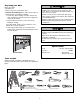
Preparing your Door Before you begin: • Disable locks. • Remove any ropes connected to door. • Complete the following test to make sure your door is balanced and is not sticking or binding: 1. Lift the door about halfway as shown. Release the door. If balanced, it should stay in place, supported entirely by its springs. 2. Raise and lower the door to see if there is any binding or sticking. If your door binds, sticks or is out of balance, call a trained door systems technician. 3.
Carton Inventory Note that accessories will depend on the model purchased. If anything is missing, carefully check the packing material. Your door operator is packaged in one carton which contains the motor unit and the parts illustrated below.
ASSEMBLY STEP 1 Attach the Collar to the Operator To prevent possible SERIOUS INJURY or DEATH, the collar MUST be properly tightened. The door may not reverse correctly or limits may be lost due to collar slip. To avoid installation difficulties, do not run the door operator until instructed to do so. • Loosen the collar screws. • Attach collar to either the left or the right side of the operator. Ensure that the collar is seated all the way on motor shaft until stop is reached (Figure 1).
WARNING INSTALLATION IMPORTANT INSTALLATION INSTRUCTIONS WARNING To reduce the risk of SEVERE INJURY or DEATH: 1. READ AND FOLLOW ALL INSTALLATION WARNINGS AND INSTRUCTIONS. 2. Install door operator ONLY on properly balanced and lubricated door. An improperly balanced door may not reverse when required and could result in SEVERE INJURY or DEATH. 3. ALL repairs to cables, spring assemblies and other hardware MUST be made by a trained door systems technician BEFORE installing operator. 4.
INSTALLATION STEP 2 Attach the Emergency Release Rope and Handle To prevent possible SERIOUS INJURY or DEATH from a falling door: • If possible, use emergency release handle to disengage door ONLY when door is CLOSED. Weak or broken springs or unbalanced door could result in an open door falling rapidly and/or unexpectedly. • NEVER use emergency release handle unless doorway is clear of persons and obstructions.
INSTALLATION STEP 4 Figure 1 Attach the Cable Tension Monitor (Required) Operator This operator comes standard with the cable tension monitor. It is supplied as a device to monitor the cables for ANY slack that may occur and will reverse the door when excessive slack is detected, eliminating service calls. The cable tension monitor MUST be connected and properly installed before the door operator will move in the down direction. NOTE: The cable tension monitor is shipped for left side installation.
INSTALLATION STEP 5 Install the Single Button Control Station To prevent possible SERIOUS INJURY or DEATH from electrocution: • Be sure power is not connected BEFORE installing door control. • Connect ONLY to 24 VOLT low voltage wires. To prevent possible SERIOUS INJURY or DEATH from a closing door: • Install door control within sight of door, out of reach of children at a minimum height of 5 feet (1.5 m) and away from ALL moving parts of door.
IMPORTANT SAFETY INSTRUCTIONS WARNING To reduce the risk of SEVERE INJURY or DEATH: 1. This portable luminaire has a polarized plug (one blade is wider than the other) as a feature to reduce the risk of electric shock. 2. This plug will fit in a polarized outlet ONLY one way. 3. If the plug does not fit fully in the outlet, reverse the plug. 4. If it still does not fit, contact a qualified electrician. 5. NEVER use with an extension cord unless plug can be fully inserted. 6. Do not alter the plug. 7.
INSTALLATION STEP 7 Electrical Requirements To prevent possible SERIOUS INJURY or DEATH from electrocution or fire: • Be sure power is not connected to the operator, and disconnect power to circuit BEFORE removing cover to establish permanent wiring connection. • Door installation and wiring MUST be in compliance with ALL local electrical and building codes. • NEVER use an extension cord, 2-wire adapter or change plug in any way to make it fit outlet. Be sure the operator is grounded.
INSTALLATION STEP 8 Mount the Standby Power Unit (SPU) (Not Provided) 475LM Standby Power System If the optional 475LM Standby Power Unit is part of this installation it should be installed at this time. • The SPU can be mounted to either the ceiling or a wall within 3' (.9 m) of the motor unit. • Position the SPU as desired to a structural support (ceiling joist or wall stud). • Attach the SPU to the support using the mounting holes on either side of the SPU.
INSTALLATION STEP 7 Install The Protector System® Be sure power is not connected to the door operator BEFORE installing the safety reversing sensor. To prevent SERIOUS INJURY or DEATH from a closing door: • Correctly connect and align the safety reversing sensor. This required safety device MUST NOT be disabled. • Install the safety reversing sensor so beam is NO HIGHER than 6" (15 cm) above floor.
INSTALLING THE BRACKETS Be sure power to the operator is disconnected. Install and align the brackets so the safety reversing sensors will face each other across the door, with the beam no higher than 6" (15 cm) above the floor. They may be installed in one of three ways, as follows. Figure 1 DOOR TRACK MOUNT (RIGHT SIDE) Door Track Lip Indicator Light Door track installation (preferred) (Figure 1): • Slip the curved arms over the rounded edge of each door track, with the curved arms facing the door.
MOUNTING AND WIRING THE SAFETY REVERSING SENSORS • Slide a 1/4"-20x1/2" carriage bolt head into the slot on each sensor. Use wing nuts to fasten safety reversing sensors to brackets, with lenses pointing toward each other across the door. Be sure the lens is not obstructed by a bracket extension (Figure 5). • Finger tighten the wing nuts. • Run the wires from both safety reversing sensors to the operator. Use insulated staples to secure wire to wall and ceiling.
ADJUSTMENT STEP 1 Program the Travel Limits Without a properly installed safety reversal system, persons (particularly small children) could be SERIOUSLY INJURED or KILLED by a closing door. • NEVER learn forces or limits when door is binding or sticking. Repair door first. • Incorrect adjustment of door travel limits will interfere with proper operation of safety reversal system. • After ANY adjustments are made, the safety reversal system MUST be tested. Door MUST reverse on contact with 1-1/2" high (3.
ADJUSTMENT STEP 2 Setting the Force Without a properly installed safety reversal system, persons (particularly small children) could be SERIOUSLY INJURED or KILLED by a closing door. • NEVER learn forces or limits when door is binding or sticking. Repair door first • Too much force on door will interfere with proper operation of safety reversal system. • After ANY adjustments are made, the safety reversal system MUST be tested. Door MUST reverse on contact with 1-1/2" high (3.
ADJUSTMENT STEP 3 Test the Safety Reversal System Without a properly installed safety reversal system, persons (particularly small children) could be SERIOUSLY INJURED or KILLED by a closing door. • Safety reversal system MUST be tested every month. • If one control (force or travel limits) is adjusted, the other control may also need adjustment. • After ANY adjustments are made, the safety reversal system MUST be tested. Door MUST reverse on contact with 1-1/2" (3.
ADJUSTMENT STEP 5 Test Cable Tension Monitor To prevent possible SERIOUS INJURY or DEATH from a falling door: • If possible, use emergency release handle to disengage door ONLY when door is CLOSED. Weak or broken springs or unbalanced door could result in an open door falling rapidly and/or unexpectedly. • NEVER use emergency release handle unless doorway is clear of persons and obstructions. If your cable tension monitor has been activated the Indicator Light will blink 9 times. See (Figure 1) page 16.
WARNING OPERATION IMPORTANT SAFETY INSTRUCTIONS WARNING To reduce the risk of SEVERE INJURY or DEATH: 1. READ AND FOLLOW ALL WARNINGS AND INSTRUCTIONS. 2. ALWAYS keep remote controls out of reach of children. NEVER permit children to operate or play with door control push buttons or remote controls. 3. ONLY activate door when it can be seen clearly, it is properly adjusted and there are no obstructions to door travel. 4. ALWAYS keep door in sight until completely closed.
CARE OF YOUR OPERATOR MAINTENANCE SCHEDULE Once a Month • Manually operate door. If it is unbalanced or binding, call a trained door systems technician. • Check to be sure door opens & closes fully. Adjust limits and/or force if necessary (see Adjustment Steps 1 and 2). • Repeat the safety reverse test. Make any necessary adjustments (see Adjustment Step 3). Once a Year • Oil door rollers, bearings and hinges. The operator does not require additional lubrication. Do not grease the door tracks.
HAVING A PROBLEM? (TROUBLESHOOTING) 1. The operator doesn't operate from either the Door Control or the remote control: • Does the operator have electric power? Plug a lamp into the outlet. If it doesn't light, check the fuse box or the circuit breaker. (Some outlets are controlled by a wall switch.) • Is there a build-up of ice or snow under the door? The door may be frozen to the ground. Remove any restriction. • The door spring may be broken. Have it replaced (see page 3 for reference). 6.
Having a Problem? (Continued) 11. The operator motor hums briefly, then won't work: • The door springs may be broken. See above. 12. The operator won't operate due to power failure: • Use the emergency release handle to disconnect the door. The door can be opened and closed manually. When power is restored, pull manual release a second time. • If a Standby Power Unit is connected, the operator should be able to operate up to 20 times without power. 13. Door loses limits. • Collar not tightened securely.
Motor Unit Installed Safety Reversing Sensor “Learn” Button LED or Diagnostic LED “Learn” Button Your garage door operator is programmed with self-diagnostic capabilities. The “Learn” button/diagnostic LED will flash a number of times then pause signifying it has found a potential issue. Consult Diagnostic Chart below. Diagnostic Chart 1 FLASH Safety reversing sensors wire open (broken or disconnected). OR 2 FLASHES Safety reversing sensors wire shorted or black/ white wire reversed.
PROGRAMMING NOTICE: If this Security✚® door operator is operated with a non-rolling code transmitter, the technical measure in the receiver of the door operator, which provides security against code-theft devices, will be circumvented. The owner of the copyright in the door operator does not authorize the purchaser or supplier of the non-rolling code transmitter to circumvent that technical measure.
To Add, Program or Change a Keyless Entry PIN (Not Provided) NOTE: The optional Keyless Entry must be programmed to operate your garage door operator. USING THE “LEARN” BUTTON 1. Press and release the purple “learn” button on motor unit. The learn indicator light will glow steadily for 30 seconds. 2. Within 30 seconds, enter a four digit personal identification number (PIN) of your choice on the keypad. Then press and hold the ENTER button. 3.
Programming Remote Light (Not Provided) The garage door operator remote light will need to be programmed to operate with the door operator. Follow the instructions below to program the light. 1. Press the “learn button” on light until LED comes ON. 2. Activate the door using the Single Button Control Station (or hand-held remote control or keyless entry, if programmed). 3. It has learned the code and the light turns on.
REPAIR PARTS Installation Parts 8 5 1 3 2 4 7 NOT ICE KEY NO. PART NO. 1 2 APBS 1 41A4582 3 4 5 6 41B4494-1 41A6104 41C0902 41A5034 6 DESCRIPTION Single button control station Emergency release rope & handle assembly 2-Conductor bell wire - white & white/red Cable tension monitor Mounting bracket Safety sensor kit (receiving and sending eyes) with 3' (.9 m) 2-conductor bell wire attached KEY NO. PART NO.
ACCESSORIES 41A5281 Extension Brackets: (Optional) For safety reversing sensor installation onto the wall or floor. 377LM Keyless Entry with Security✚®: Enables end user to operate door operator from outside by entering a password on a specially designed keyboard. Also can add a temporary password for visitors or service persons. This temporary password can be limited to a programmable number of hours or entries.
NOTES 31
LIFTMASTER® SERVICE IS ON CALL HOW TO ORDER REPAIR PARTS OUR LARGE SERVICE ORGANIZATION SPANS AMERICA Selling prices will be furnished on request or parts will be shipped at prevailing prices and you will be billed accordingly. INSTALLATION AND SERVICE INFORMATION IS AS NEAR AS YOUR TELEPHONE. SIMPLY DIAL OUR TOLL FREE NUMBER: WHEN ORDERING REPAIR PARTS, ALWAYS GIVE THE FOLLOWING INFORMATION: • PART NUMBER • PART NAME 1-800-528-2806 • MODEL NUMBER ADDRESS ORDERS TO: THE CHAMBERLAIN GROUP, INC.