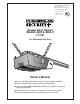
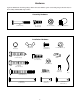
The Chamberlain Group, Inc. A DUCHOSSOIS ENTERPRISE 845 Larch Avenue Elmhurst, Illlinois 60126-1196 www.chamberlaingroup.com Complies with UL 325 regulations effective January 1, 1993 ® Garage Door Opener Models 4620 & 4620-2 1/2 HP For Residential Use Only Owner’s Manual ■ Please read this manual and the enclosed safety materials carefully! ■ Fasten the manual near the garage door after installation. ■ The door WILL NOT CLOSE unless the Protector System® is connected and properly aligned.
Contents Safety alert symbol review............................................2 Safety information, precautions, tools ..........................3 Testing your garage door for binding & balance ..........3 Carton inventory ...........................................................4 Hardware inventory.......................................................5 Illustration of sectional door installation .....................6 Illustration of one-piece door installation .....................
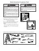
Safety Information, Precautions, Tools WARNING CAUTION An unbalanced garage door might not reverse when required and someone under the door could be seriously injured or killed. If your garage door binds, sticks or is out of balance, call for professional garage door service. Garage doors, door springs, cables, pulleys, brackets, and their hardware are under extreme tension and can cause serious injury or death.
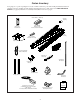
Carton Inventory Your garage door opener is packaged in one carton which contains the power unit and all parts illustrated below. If anything is missing, carefully check the packing material. Parts may be "stuck" in the foam. KEEP THE FOAM INTACT (see page 10). Hardware for assembly and installation is shown on page 5.
Hardware Separate all hardware from the packages in the rail carton and the opener carton and group as shown below, for the assembly and installation procedures.
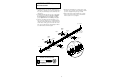
SECTIONAL Door Installation Before you begin, survey your garage area to see whether any of the conditions below apply to your installation. You may find it helpful to refer back to this page as you proceed with the installation of your opener. FINISHED CEILING Support bracket & fastening hardware is required. See page 20. Horizontal and vertical reinforcement is needed for lightweight garage doors (fiberglass, steel, aluminum, door with glass panels, etc.). See page 24 for details.
ONE-PIECE Door Installation Before you begin, survey your garage area to see whether any of the conditions below apply to your installation. You may find it helpful to refer back to this page as you proceed with the installation of your opener. FINISHED CEILING Support bracket & fastening hardware is required. See page 20.
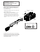
Assembly Section: Pages 8 - 11 ASSEMBLY STEP 1 To avoid installation difficulties, do not run the garage door opener until instructed to do so. Assemble the Rail Straight Door Arm Extend End Rails Outward Rail Support Braces Remove Cardboard Packing Center Rail Trolley Rack Rail Assembly Hardware Bag Rail Assembly Carton Remove Cardboard Packing Chassis Assembly Hardware Bag Extend End Rails Outward 1. Turn the opened rail carton upside down, emptying its contents onto a level work surface. 2.
ASSEMBLY STEP 1 (Continued) Assemble the Rail The Chamberlain Group, Inc. 4. Beginning with the sprocket end, straighten the two ScrewrailDrive LMso that the screw rod is in a straight line at sections 3-Piece Rail (Avoid handling the joints, which may have the joint. sharp Align Railsedges.) & Attach Support Brackets 5. Carefully slide-the pins at the top edge of the rail into 8/7/94 - 8/10/94 9/12/94 - 1/12/95 7.
ASSEMBLY STEP 2 Fasten the Rail To the Power Unit and Install the Trolley NOTE: To aid in assembly and installation, replace the foam packing around the power unit. Remove it /7/94 after Installation Step 5. • Working on a level surface, align the rail assembly with the power unit, as shown. • Slip the coupling over the rail sprocket. • Slide the rail through the power unit bracket until the coupling fits securely over the power unit sprocket.
ASSEMBLY STEP 3 Attach the Rail Brackets • Align rail brackets to end of rail assembly, as shown. • Insert two 1/4"-20 x 5/8" hex screws and lock nuts. Tighten securely with a 7/16" socket. Rail Brackets 1/4"-20 Lock Nuts Hardware Shown Actual Size 1/4" - 20 x 5/8" Hex Screw 1/4" - 20 Lock Nut 1/4"-20x5/8 Hex Screws Rail You have now finished assembling your garage door opener.
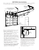
Installation Section: Pages 12 – 27 Installation Step 1 WARNING Determine Header Bracket Location If the header bracket is not rigidly fastened to a structural support on the header wall or ceiling, the safety reverse system may not work properly (see page 30). The door might not reverse when required, and could cause serious injury or death. The garage door springs, cables, pulleys, brackets and their hardware are under extreme tension. Do not attempt to loosen, move or adjust them yourself.
Position Header Bracket One Piece Door Without Track 1/30/92 - 4/7/92 ONE-PIECE Door Without Track Read the Safety Instructions on page 12. They also apply to doors without tracks. Unfinished Ceiling Header Wall • Close the door and mark the inside Vertical vertical centerline of your garage door. Centerline 2x4 Extend the line onto the header wall above door. If headroom clearance is minimal, you can install the header bracket on the The Chamberlain Group, Inc. ceiling. See page 14.
Installation Step 2 Install the Header Bracket You can attach the header bracket either to the wall above the garage door, or to the ceiling. Follow the instructions which will work best for your particular requirements. Fastening the Header Bracket to the Wall Fastening the Header Bracket to the Ceiling • Center the bracket on the vertical guideline with the bottom edge of the bracket on the horizontal line as shown (with the arrow pointing toward the ceiling).
Installation Step 3 Attach the Rail to the Header Bracket The Chamberlain Group, Inc. Foam/Rail to Header Bracket New Rail Assy. 12/6/94 • Position the opener on the garage floor below the header bracket. Use packing material as a protective base. If the door spring is in the way you’ll need help. Have someone hold the opener securely on a temporary support to allow the rail to clear the spring. • Position the rail bracket against the header bracket.
The Protector System® IMPORTANT INFORMATION ABOUT THE SAFETY REVERSING SENSOR WARNING The safety reversing sensor must be connected and aligned correctly before the garage door opener will move in the down direction. This is a required safety device and cannot be disabled. Without a properly working safety reversing sensor, persons (particularly children) could be injured or killed by a closing garage door. Read and follow all instructions.
Installation Step 4 Install the Safety Reversing Sensor (Receiving and Sending Eyes) INSTALLING THE BRACKETS Be sure power to the opener is disconnected. Install and align the brackets so the sensors will face each other across the garage door, with the beam from 4 – 6" above the floor. Figure 1 DOOR TRACK MOUNT (Right Side) Door Track Lip They may be installed in one of three ways, as follows.
Installation Step 4 (Continued) Install the Safety Reversing Sensor Figure 4 Mounting and Wiring the Safety Sensors • Slide a 1/4"-20x1/2" carriage bolt head into the slot on each sensor. Use wing nuts to fasten sensors to brackets, with lenses pointing toward each other across the door. Be sure the lens is not obstructed by a bracket extension. See Figure 4. • Finger tighten the wing nuts. Wing nut 1/4"-20x1/2" Carriage bolt Recommended Wire Routing 1.
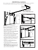
Installation Step 5 CAUTION Position the Opener To prevent damage to steel, aluminum, fiberglass or glass panel doors, do not rest the opener on the door without using a 2x4. Follow instructions which apply to your door type as illustrated. SECTIONAL Door or ONE-PIECE Door with Track A 2x4 laid flat is convenient for setting an ideal doorto-rail distance. • Raise the opener onto a stepladder. You will need help at this point if the ladder is not tall enough.
The Chamberlain Installation Step 6 Group, Inc. WA WARNING Drive Liftmaster #114A1794 Hang theScrew Opener Hang Opener Chassis 6/18/94 The opener could fall and injure someone if it is not properl y secured. Fasten the opener securel y to structural supports of the garage. Two representative installations are shown. Yours may be different. Hanging brackets should be angled, Figure 1, to provide rigid support.
Installation Step 7 WARNING Install the Door Control and Connect all Wiring Children operating or playing with a garage door opener can injure themselves or others. The garage door could close and cause serious injury or death.
Installation Step 8 WARNING Electrical Requirements To prevent electrocution or fire, installation and wiring must be in compliance with local electrical and building codes. Do NOT use an extension cord, 2-wire adapter, or change the plug in any way to make it fit your outlet. To reduce the risk of electric shock, your garage door opener has a grounding type plug with a third grounding pin. This plug will only fit into a grounding type outlet.
Installation Step 10 Install the Lights and Lens 100 Watt Max. Light Bulb • Install a 100 watt maximum light bulb in each socket. The lights will turn ON and remain lit for approximately 4-1/2 minutes when power is connected. Then the lights will turn OFF. • Insert bottom lens tabs into slots on chassis and tilt towards chassis to engage top tabs, then drop down gently into place. (See illustration.) • To remove, lift lens up and gently tilt slightly outward and down, then pull out to clear bulbs.
Installation Step 12 CAUTION Fasten Door Bracket To prevent damage to steel, aluminum, fiberglass or glass panel doors, always reinforce the inside of the door both vertically and horizontally with an angle iron. Follow instructions which apply to your door type as illustrated below or on page 25. A horizontal brace should be long enough to be secured to 2 vertical supports. A vertical brace should cover the height of the top panel.
All ONE-PIECE Door Installation Procedure Please read and comply with the warnings and reinforcement instructions on page 24. They apply to one-piece doors also. Header Wall 2x4 Support Finished Ceiling Horizontal and vertical reinforcement is needed for lightweight garage doors (fiberglass, aluminum, steel, door with glass panel, etc.).
Installation Step 13 Connect Door Arm to Trolley Follow instructions which apply to your door type as illustrated below and on page 27. SECTIONAL Doors Only DoorArmTrolleySecScrew Make6/96 sure garage door is fully closed. Pull the manual release handle to disconnect the outer trolley from the inner trolley. Slide the outer trolley back (away from the door) about 2" as shown in Figures 1, 2 and 3. Figure 1: • Fasten straight door arm section to outer trolley with the 5/16"x1" clevis pin.
All ONE-PIECE Doors Ring Fastener Door Bracket Assemble the Door Arm: Lock Washers 5/16" • Fasten the straight and curved door arm sections together to the longest possible length (with a 2 or 3 hole overlap). • With the door closed, connect the straight door arm section to the door bracket with the 5/16"x1-1/4" clevis pin. • Secure with a ring fastener.
The Chamberlain Group, Inc. Screw Drive LM 114A1794 Adjustment Limit Adjustments 5/4/94, 5/18/94 - 6/5/94 Section: Pages 28 – 30 Adjustment Step 1 WARNING WARNING Adjust the UP and DOWN Limits Improper adjustment of the travel limits will interfere with the proper operation of the safety reverse system. The door might not reverse properly when required and could seriously injure or kill someone under it. Test the safety reverse system monthly, and following all adjustments to the travel limits.
Adjustment Step 2 WARNING Adjust the Force Too much force on the door will interfere with the proper operation of the safety reverse system. The door might not reverse properly when required and could seriously injure or kill someone under it. Do not increase the force beyond the minimum amount required to close the door. Do not use the force adjustments to compensate for a binding or sticking garage door. Test the safety reverse system monthly, and following all adjustments to force levels. See page 30.
Adjustment Step 3 WARNING Test The Protector System ® Without a properly working safety reversing sensor, persons (particularly children) could be seriously injured or killed if trapped by a closing garage door. Repeat this test once a month. • Press the remote control push button to open the door. • Place the opener carton in the path of the door. • Press the remote control push button to close the door. The door will not move more than an inch, and the opener light will flash for 5 seconds.
IMPORTANT SAFETY INSTRUCTIONS WARNING WARNING To reduce the risk of severe injury or death to persons: 1. READ AND FOLLOW ALL INSTRUCTIONS. 2. Do not permit children either to operate or to play with the opener. Keep remote control in a location inaccessible to children. 3. Operate opener only when the door is in full view and free from any obstruction. Keep the door in sight until it is completely closed. NO ONE SHOULD CROSS THE PATH OF THE MOVING DOOR. 4. Check safety reversal system monthly.
Operation of Your Opener Activate the opener with any of the following: • The Remote Control Transmitter. Hold push button down until the door starts to move. • The Door Control. Hold push button down until the door starts to move. • The Outside Keylock or Keyless Entry. (See Accessories) WARNING Weak or broken springs could allow an open door to fall (either rapidly or unexpectedly), resulting in serious injury, death or property damage.
Receiver and Remote Control Programming NOTICE: To comply with FCC rules, adjustment or modification of this receiver and/or transmitter are prohibited, except for changing the code setting or replacing the transmitter battery. THERE ARE NO OTHER USER SERVICEABLE PARTS. Your garage door opener receiver and remote control have been pre-set at the factory. The door will open when you press the remote control push button.
Having a Problem? Situation Probable Cause & Solution The opener doesn't operate from either the door control or the remote control: 1. Does the opener have electric power? Plug a lamp into the outlet. If it doesn't light, check the fuse box or the circuit breaker. (Some outlets are controlled by a wall switch.) 2. Have you disabled all door locks? Review installation instruction warnings on Page 11. 3. Is there a build-up of ice or snow under the door? The door may be frozen to the ground.
Having a Problem? (continued) Situation Probable Cause & Solution The door opens but won't close: 1. If the opener lights blink, check the safety reversing sensor. See page 22. 2. If the opener lights do not blink and it is a new installation, check the down force. See Adjustment Step 2, page 29. For an existing installation, see below. Repeat the safety reverse test after the adjustment is complete. The door reverses for no apparent reason and opener lights don't blink: 1.
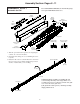
Repair Parts Rail Assembly Parts 9 1 10 2 8 7 4 KEY PART NO. NO. 1 2 3 5 41A4796 41A4795 3 4 5 6 7 8 9 10 6 DESCRIPTION Hardware bag Hardware bag (includes sprocket coupling) 12B569-1 Left rail bracket 12B569-2 Right rail bracket 1C4827-1 Screw drive rail assembly 12B560 Rail support brace 81C168 Rack 41C4677 Complete trolley assembly 25A18 Sprocket coupling 41A4836 Drive sprocket kit Installation Parts 2 1 4 6 5 3 NOT ICE KEY NO. PART NO.
Repair Parts Opener Assembly Parts ew crew Drive (Down) Contact Brown Wire 2 1 DN UP 2/94 LIMIT SWITCH ASSY. Drive Gear Center Limit Contact 4 5 Yellow Wire 3 6 7 8c (Up) Contact Grey Wire 8a 9 8d 10 8b 8 11 12 13 17 14 15 16 KEY PART NO. NO. DESCRIPTION 1 2 3 4 5 6 7 8 8a 8b 8c Drive shaft cover Line cord Capacitor – 1/2 HP Capacitor bracket Terminal block w/screws Limit switch assembly Limit switch bracket Complete Motor Drive Assy.
Accessories Available For Your Opener 950CB SECURITY✚ Single-Function Remote Control: Includes visor clip. 956CB SECURITY✚ Multi-Function Mini Remote Control: With key ring and Velcro fastening strip. 953CB SECURITY✚ Multi-Function Remote Control: Includes visor clip. 7702CB Outside Quick Release: Required for a garage with NO access door. Enables homeowner to open garage door manually from outside by disengaging trolley.
Index Access Door/Outside Quick Release Accessory .................................................................................................6, 7, 35, 36 Electrical Safety Warnings ......................................................................................................................................2, 22, 31 Garage Door Testing for balance, binding and sticking.................................................................................................................
CHAMBERLAIN SERVICE IS ON CALL OUR LARGE SERVICE ORGANIZATION SPANS AMERICA INSTALLATION AND SERVICE INFORMATION IS AS NEAR AS YOUR TELEPHONE SIX DAYS A WEEK. SIMPLY DIAL OUR TOLL FREE NUMBER: HOW TO ORDER REPAIR PARTS Selling prices will be furnished on request or parts will be shipped at prevailing prices and you will be billed accordingly. WHEN ORDERING REPAIR PARTS, ALWAYS GIVE THE FOLLOWING INFORMATION: • PART NUMBER • PART NAME • MODEL NUMBER 1-800-528-9131 HOURS: (Central Standard Time) 6:00 A.M.