OWNER’S MANUAL & OPERATING INSTRUCTIONS 3400 Starting watts / 3100 Running watts Wireless remote, electric start Limited Wa rra Year n ree SAVE THESE INSTRUCTIONS Important Safety Instructions are included in this manual. n tí a li m 100261 os Ga ra MODEL NUMBER ty Th PORTABLE INVERTER GENERATOR e it a d a d e tr sa ñ MADE IN CHINA REV 100261-20161208 12039 Smith Ave. Santa Fe Springs CA 90670 USA 1-877-338-0999 www.championpowerequipment.
FCC Statement 1. This device complies with Part 15 of the FCC Rules. Operation is subject to the following two conditions: (1) This device may not cause harmful interference. (2) This device must accept any interference received, including interference that may cause undesired operation. 2. Changes or modifications not expressly approved by the party responsible for compliance could void the user’s authority to operate the equipment.
100261 3400 Starting Watts / 3100 Running Watts Wireless Remote, electric start PORTABLE INVERTER GENERATOR TABLE OF CONTENTS Introduction . . . . . . . . . . . . . . . . . . . . . . Introduction . . . . . . . . . . . . . . . . . . . . Portable Power Generator . . . . . . . . . . . Accessories . . . . . . . . . . . . . . . . . . . . This Booklet . . . . . . . . . . . . . . . . . . . . Manual Conventions. . . . . . . . . . . . . . . . . Safety Rules . . . . . . . . . . . . . . . . . . . . . .
ENGLISH 100261 INTRODUCTION Introduction Congratulations on your purchase of a Champion Power Equipment product. Champion Power Equipment and Champion Engine Technology designs, builds, and supports all of our products to strict specifications and guidelines. With proper product knowledge, safe use, and regular maintenance, this product should bring years of satisfying service.
100261 ENGLISH MANUAL CONVENTIONS This manual uses the following symbols to help differentiate between different kinds of information. The safety symbol is used with a key word to alert you to potential hazards in operating and owning power equipment. Follow all safety messages to avoid or reduce the risk of serious injury or death. DANGER DANGER indicates an imminently hazardous situation which, if not avoided, will result in death or serious injury.
ENGLISH 100261 SAFETY RULES WARNING Read this manual thoroughly before operating your generator. Failure to follow instructions could result in serious injury or death. WARNING The engine exhaust from this product contains chemicals known to the state of California to cause cancer, birth defects, or other reproductive harm. DANGER Generator exhaust contains carbon monoxide, a colourless, odourless, poison gas. Breathing carbon monoxide will cause nausea, dizziness, fainting or death.
100261 ENGLISH DANGER SAFETY RULES WARNING Fuel and fuel vapours are highly flammable and extremely explosive. Fire or explosion can cause severe burns or death. Unintentional startup can result in entanglement, traumatic amputation or laceration. Rapid retraction of the starter cord will pull hand and arm towards the engine faster than you can let go. Unintentional startup can result in entanglement, traumatic amputation or laceration. Broken bones, fractures, bruises or sprains could result.
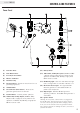
ENGLISH 100261 464 CONTROLS AND FEATURES Read this owner’s manual before operating your generator. Familiarize yourself with the location and function of the controls and features. Save this manual for future reference. Generator 637 6 1 2 3 4 637 5 8 (1) Fuel Cap – Remove to add fuel. (5) Muffler (2) Recoil Starter – Used to start the engine. (6) Carrying Handle (3) Power Panel (7) Maintenance Cover (4) Foldaway Handle – Do not use the foldaway handle to lift or carry the unit.
100261 ENGLISH CONTROLS AND FEATURES Power Panel 16 12 11 15 14 13 1 8 2 3 8 4 10 5 6 7 9 (1) Fuel Valve Knob (11) Battery Switch (2) Push-Button Choke (3) Economy Control Switch (4) Wireless Set Button (12) 120 Volt AC, 30 Amp Receptacle (NEMA TT-30R) – May be used to supply electrical power for the operation of 120 Volt AC, 30 Amp, single phase 60 Hz electrical loads. (5) Red Pilot Lamp (6) Ground Terminal – Consult an electrician for local grounding regulations.
ENGLISH 100261 CONTROLS AND FEATURES Safety Label Locations These labels warn you of potential hazards that can cause serious injury. Read them carefully. If a label comes off or becomes hard to read, contact Champion Power Equipment’s customer service department for possible replacement.
100261 ENGLISH CONTROLS AND FEATURES Wireless Remote Control This generator is equipped with a wireless remote control system for starting and stopping. The system consists of (4) main components: 1. Receiver Control Module (RCM) 2. Wireless Remote 3. Battery Switch 4. Ignition Switch The Remote Control functions are enabled when: 1. The Ignition Switch is in the “ON” position, AND 2. The Battery Switch is in the “ON” position.
ENGLISH 100261 ASSEMBLY Your generator requires some assembly. This unit ships from our factory without oil. It must be properly serviced with fuel and oil before operation. If you have any questions regarding the assembly of your generator, call our help line at 1-877-338-0999. Please have your serial number and model number available. Remove the Generator from the Shipping Carton 1. Set the shipping carton on a solid, flat surface. 2. Remove everything from the carton except the generator. 3.
100261 ENGLISH Add Engine Oil ASSEMBLY Add Engine Oil Cont’d. CAUTION Degrees Celsiusº (Outside) DO NOT attempt to crank or start the engine before it has been properly filled with the recommended type and amount of oil. Damage to the generator as a result of failure to follow these instructions will void your warranty. Full Synthetic 5W-30 NOTE The recommended oil type is 10W-30 automotive oil. Degrees Fahrenheitº (Outside) 1. Place the generator on a flat, level surface. 2.
ENGLISH 100261 ASSEMBLY Add Fuel 1. 2. 3. 4. 5. 6. Use clean, fresh, regular unleaded fuel with a minimum octane rating of 85 and an ethanol content of less than 10% by volume. DO NOT mix oil with fuel. Clean the area around the fuel cap. Remove the fuel cap. Slowly add fuel to the tank. DO NOT OVERFILL. Fuel can expand after filling. A minimum of 1/4 in. (6.4 mm) of space left in the tank is required for fuel expansion, more than 1/4 in. (6.4 mm) is recommended.
100261 ENGLISH OPERATION Generator Location Grounding NEVER operate the generator inside any building, including garages, basements, crawlspaces and sheds, enclosure or compartment, including the generator compartment of a recreational vehicle. Please consult your local authority. In some areas, generators must be registered with the local utility. Generators used at construction sites may be subject to additional rules and regulations.
ENGLISH 100261 OPERATION Electric and Recoil Start 1. 2. 3. Make certain the generator is on a flat, level surface. Disconnect all electrical loads from the generator. Never start or stop the generator with electrical devices plugged in or turned on. Turn the fuel valve to the “On” position. Electric and Recoil Start Cont’d. 8. 9. within five seconds, release the switch and wait at least ten seconds before attempting to start the engine again.
100261 ENGLISH OPERATION Manual Choke Start Manual Choke Start Cont’d. If the battery is dead or not able to produce enough current to power the push button choke, the choke itself can be operated manually to help start the engine. To manually choke and start the inverter, follow these steps: 1. Loosen the screws and remove the maintenance cover. (A) A NOTE Keep choke lever in “Choke” (right) position for only 1 pull of the recoil starter.
ENGLISH 100261 OPERATION Connecting Electrical Loads 12V DC Outlet 1. The 12V DC outlet can be used with the supplied charge cable and USB charger and other commercially available 12V DC automotive style plugs. The DC output is unregulated and can damage some products. Confirm your accessory input voltage range is at least 12-24V DC. When using the DC outlet turn the Economy mode switch to the “OFF” position. 2.
100261 ENGLISH OPERATION Do Not Overload Generator Operation at High Altitude Capacity The density of air at high altitude is lower than at sea level. Engine power is reduced as the air mass and airfuel ratio decrease. Engine power and generator output will be reduced approximately 3½% for every 1000 feet of elevation above sea level. This is a natural trend and cannot be changed by adjusting the engine.
ENGLISH 100261 OPERATION Wireless Set Button Parallel Operation The wireless set button is a feature that lets the user sync remotes to the generator. One can set up to two remote controls or reset a remote control with the generator. To reset a remote control or sync two remote controls follow these steps: 1. Turn the ignition switch to the “ON” position. 2. Turn the battery switch to the “ON” position. 3.
100261 ENGLISH The owner/operator is responsible for all periodic maintenance. MAINTENANCE AND STORAGE Oil Cont’d. NOTE WARNING Once oil has been added, a visual check should show oil about 1-2 threads from running out of the fill hole. If using the dipstick to check oil level, DO NOT screw in the dipstick while checking. Never operate a damaged or defective generator. WARNING Tampering with the factory set governor will void your warranty. WARNING Improper maintenance will void your warranty.
ENGLISH 100261 MAINTENANCE AND STORAGE Air Filter Adjustments 1. 2. 3. 4. 5. 6. 7. The air-fuel mixture is not adjustable. Tampering with the governor can damage your generator and your electrical devices and will void your warranty. CPE recommends that you contact our service line at 1-877-338-0999 for all other service and/or adjustment needs. Remove the maintenance cover. Locate the air filter plastic cover. Unsnap the locking hinge on the cover. Remove the old filter.
100261 ENGLISH MAINTENANCE AND STORAGE Charge the Battery Generator Maintenance Cont’d. For a generator equipped with batteries for electric starting, proper battery maintenance and storage should be followed. An automatic battery charger (not included) with automatic charging capability should be used to charge the battery. Maximum charging rate should not exceed 1.5 amps. Follow the instructions included with the battery charger. The battery should be fully charged at least once per month.
ENGLISH 100261 SPECIFICATIONS Spark Plugs Engine Specifications – – – – Model . . . . . . Displacement . Type . . . . . . . Start Type . . . . . . . . . . . . . . . . . . . . . . . . . . . . . . . . . . . . . . . . . . . . . . . . . . . . . . . . . . . . . YF170FD-331 . . . . . . . . 192cc . . .4-Stroke OHV . Wireless Remote Generator Specifications Maintenance Valve Clearance – Model . . . . . . . . . . . . . . . . . . . . . . . . . . 100261 – Running watts . . . . . . . . . . . . . .
100261 ENGLISH SPECIFICATIONS Wiring Diagram OFF ST ON 3 4 6 C 30 3 0 ST OFF 6 4 120V TT-30R M 120V 5-20R 0 22
23 0 0 0 07 06 0 04 03 4 4 0 3 47 0 46 4 4 3 44 0 0 00 43 4 6 4 3 6 40 7 7 43 3 3 4 4 6 30 0 3 7 3 37 3 6 7 4 4 33 36 3 3 34 4 43 3 4 0 6 36 7 6 77 76 4 7 74 73 7 7 70 6 6 6 6 7 7 0 0 3 3 4 36 67 6 3 7 66 6 64 63 4 0 6 3 6 4 3 37 3 3 33 34 3 36 3 30 7 6 37 60 44 4 43 4 46 3 4 47 4 4 4 0 4 7 3 40 6 4 SPECIFICATIONS ENGLISH 100261 Parts Diagram
100261 ENGLISH Parts List # Part Number Description 1 2 83.200205.02 2.08.055.1 3 83.200204.02.2 4 2.08.052.1 5 1.9074.4.0516.1 6 7 8 9 10 83.200201.02.2 83.200206.02 1.845.4216 1.5789.0612 83.201600.06 11 1.9074.4.0512.1 12 13 14 15 16 83.200701.02.2 83.200500.01.2 83.200502.01 83.070100.01 2.06.016 17 83.070011.01 18 19 20 21 22 23 24 2.06.018 111.070300.01 2.08.068.2 83.071000.01 83.070300.01 83.070014.01 1.845.4213 25 83.081400.01 26 27 28 29 30 31 83.081004.01 2.02.001 28.
ENGLISH 100261 SPECIFICATIONS # 25 Part Number Description 117 1.845.4819 118 83.070011.02 119 120 121 122 123 124 125 126 127 128 5.1820.001 1.845.3516 1.97.1.04 5.1830.006 83.200101.02.2 100262.21 5.1110.005 83.210001.00.3 83.210001.00.1 83.019.34.45 129 1.9074.4.0414.1 130 5.1200.308 131 5.1120.010 132 5.1210.920 133 5.1210.930 134 135 122.210003.01 100262.21.10 136 1.9074.4.0512 137 1.9074.4.0535 138 139 140 141 142 143 144 145 146 147 148 149 150 151 152 153 154 155 83.
100261 ENGLISH SPECIFICATIONS This page intentionally left blank.
27 3 4 6 7 0 3 0 3 4 4 47 46 3 4 44 4 43 4 6 4 0 40 7 3 3 7 37 4 6 6 0 60 6 36 4 6 3 34 7 0 63 64 6 3 0 33 06 3 66 67 6 4 6 70 7 7 7 6 0 73 3 74 3 0 7 0 76 00 0 7 6 4 30 77 7 7 07 34 0 04 4 03 SPECIFICATIONS ENGLISH 100261 Engine Parts Diagram
100261 ENGLISH Engine Parts List # Part Number Description Qty # Part Number Description Qty 1 1.5789.0835 Flange Bolt M8 x 35 6 57 83.032000.00 Hose, Oil Drain 1 2 2.11.014 Oil Seal 2 58 28.030009.00 Gasket, Cylinder Head 1 3 83.030007.01 Cover, Crankcase 1 59 2.04.003 Dowel Pin, Ø10 x 14 2 4 83.127000.01 Oil Level Sensor 1 60 83.040006.01 Valve, Exhaust 1 5 1.5789.0612 Flange Bolt M6 x 12 11 61 83.040002.01 Valve, Intake 1 6 83.030010.
ENGLISH 100261 TROUBLESHOOTING Problem Cause Solution Generator will not start No fuel Add fuel Faulty spark plug Replace spark plug Unit loaded during start up Remove load from unit Low oil level Fill crankcase to the proper level Generator will not start; Generator starts but runs roughly Generator will not start wirelessly Generator will not start electrically Generator shuts down during operation Generator cannot supply enough power or overheating No AC output Repeated circuit breaker
WARRANTY WARRANTY* CHAMPION POWER EQUIPMENT 3 YEAR LIMITED WARRANTY Warranty Qualifications Champion Power Equipment (CPE) will register this warranty upon receipt of your Warranty Registration Card and a copy of your sales receipt from one of CPE’s retail locations as proof of purchase. Please submit your warranty registration and your proof of purchase within ten (10) days of the date of purchase.
Champion Power Equipment, Inc. (CPE), The United States Environment Protection Agency (U.S. EPA.) and the California Air Resources Board (CARB) Emission Control System Warranty Your Champion Power Equipment (CPE) engine complies with both the U.S. EPA and state of California Air Resources Board (CARB) emission regulations.
EMISSION CONTROL SYSTEM WARRANTY The following are specific provisions relative to your Emission Control System (ECS) Warranty Coverage. 1. APPLICABILITY: This warranty shall apply to 1995 and later model year California small off-road engines (for other states, 1997 and later model year engines). The ECS Warranty Period shall begin on the date the new engine or equipment is delivered to its original, end-use purchaser, and shall continue for 24 consecutive months thereafter. 2.
EMISSION-RELATED PARTS INCLUDE THE FOLLOWING: (using those portions of the list applicable to the engine) Systems covered by this warranty Fuel Metering System Fuel regulator, Carburetor and internal parts Air Induction System Air cleaner, Intake manifold Ignition System Spark plug and parts, Magneto ignition system Exhaust System Exhaust manifold, catalytic converter Miscellaneous Parts Tubing, Fittings, Seals, Gaskets, and Clamps associated with these listed systems.