
Assembly Instructions

Model 100237
INSTALLATION
29
Part No. 101951
!
CAUTION
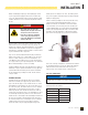
Check for leaks by spraying all connection points
with a soap solution made of dish washing soap
and water. If you see soap bubbles, this would be an
indication of a leak and it should be corrected. Check
each connection point, there should not be a visible
bubbling with the soap solution applied. Refer to the
“Fuel Pipe Sizing Chart” contained in this manual or
the Installation Manual for your specific HSB model.
Installed piping must be properly purged and leak
tested, in accordance with applicable codes and
standards.
Champion HSB units have been run and tested at the factory
prior to shipment. They do not require any type of break-in
period.
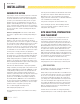
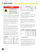
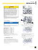
FUEL PIPE SIZING CHART
NOTICE
Reduced pipe size will affect fuel delivery and performance.
Measure the pipe length from the generator fuel inlet to the
primary gas pressure regulator.
Pipe Length* LPG
25 ft (8 m) 3/4 in. NPT
50 ft (15 m) 3/4 in. NPT
100 ft (30 m) 1 in. NPT
150 ft (46 m) 1 in. NPT
200 ft (61 m) 1 in. NPT
*Add 2.5 ft (0.76 m) per bend, tee or angle in the pipe line to
overall distance, for each 90 degree elbow, add 8 feet (2.4 m) to
the overall measurement.
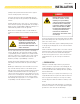
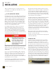
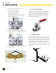
5. CONVERTING TO LPG
The engine is fitted with a dual Master Mixer Assembly
(carburetor system), which allows the HSB to run on either NG or
LPG. It has been configured at the factory to run on NG. If your
installation requires to run on LPG, an orifice in the Master Mixer
Assembly (carburetor system) must be changed. The LPG orifices
are shipped with the HSB.
1. Remove breather tube (1) by loosening breather tube
clamp (2).
2. Remove fuel inlet chamber screws (3). Remove fuel inlet
chamber (4) along with fuel hose (5) and gasket (6).
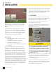
3. Remove left side main jet (7), right side main jet (8), left
side slow jet (9) and right side slow jet (10).
Recommend tool for removing main jet: Special Tool (Part
number 100908)
Recommend tool for removing slow jet: Driver Bit, 7/32
Slot - Flat Head
L
R