
Assembly Instructions


Model 100237
INSTALLATION
50
Part No. 101951
CIRCUIT BREAKERS FOR UTILITY MAIN
CONTROL PANEL AND ATS
The Utility Main Control Panel requires a double-pole circuit
breaker as a feeder for the ATS. Refer to inside label/decal on the
ATS enclosure front panel for recommendations.
ATS branch circuit breakers must match the Utility Main Control
breakers amp rating to which they will provide power outage.
Refer to the inside label/decal on the ATS front panel for
recommendations.
ELECTRICAL GROMMET(S)
Grommets can be used in any enclosure knockout for NEMA 1
installations. Grommets can only be used in the bottom enclosure
knockouts for NEMA 3R installations, when installed outside.
INSTALLATION WIRING FOR ATS TO
UTILITY MAIN CONTROL PANEL
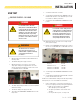
!
WARNING
!
The manufacturer recommends
that a licensed electrician or an
individual with complete knowledge
of electricity perform these
procedures. Be certain that the
power from the main panel is turned
“OFF” and all backup sources are
locked out prior to removal of the
cover or removal of any wiring of the
utility main electrical distribution
panel. Failure to do so could result
in serious injury or death. Automatic
start generators will start upon loss
of utility main power unless locked
in the “OFF” position.
!
WARNING
The wires connected to the service
main circuit breaker remain LIVE and
HOT. Avoid contact with these wires
and the service main circuit breaker
connection lugs.
!
CAUTION
Consult all local and National electric codes for proper
wiring methods for all wiring.
1. Conductor sizes must be adequate to handle the
maximum current to which they will be subjected. The
installation must comply fully with all applicable codes,
standards and regulations. Conductors must be properly
supported, of approved insulation materials, protected by
approved conduit and with the correct wire gauge size in
accordance with all applicable codes. Before connecting
wire cables to terminals, remove any surface oxides from
the cable ends with a wire brush. All power cables must
enter the enclosure through the enclosure knockouts.
2. Determine where the flexible, liquid tight conduit will pass
through the building from the inside to outside. When you
are certain that there is adequate clearance on each side
of the wall, drill a small pilot hole through the wall to mark
the location. Drill an appropriate sized hole through the
sheathing and siding.
3. In compliance with all local electrical codes, route the
conduit along ceiling/floor joists and wall studs to the
location where the conduit will pass through the wall
to the exterior of the house. Once the conduit is pulled
through the wall and in proper position to attach to the
HSB generator, place silicone caulk around the conduit on
both side of the hole, inside and outside.
4. Mount the ATS next to the Utility main circuit control panel
board (circuit breaker or fuse box). Install a large diameter
conduit (1 or 1 ¼ inch, trade size recommended, liquid
tight, (1 foot suggested distance) between the two panels.
Install a 50 ampere double-pole circuit breaker in the
Utility main circuit control panel.
5. Strip wires ½ inch and install a Black L1, and Red L2
wire suitable for 50 amperes between the double-pole
feeder breaker in the main panel and the similarly-colored
terminals on the Utility Supply terminal block in the ATS.
Install an insulated White wire of the same AWG between
the neutral bar in the main panel and the White terminal
on the Utility Supply terminal in the ATS. The Neutral wire
must be the ampacity as the L1 and L2 power wire. Install
a suitable Ground wire between the ground busses in the
two panels.
6. Select the circuits to be powered by the HSB backup
generator. If the branch circuit conductor is long enough,
you may want to pull it from the main panel board and
reinstall it in the ATS. It is possible to use an additional
wire and wire connector to extend the branch conductor