
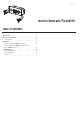
Operators Manual


3
ENGLISH 100319
OPERATION
Paralleling Two 2800W+ Inverters
1. Inverters to be turned off and all electrical loads
disconnected before installing parallel kit.
2. Align the inverters in the same direction in a “V”
configuration at a minimum of 18 in. [45 cm] apart.
3. Clamp the parallel kit to the left handle of the
inverter on the left of the “V”.
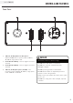
4. On each inverter, remove the connector end cap and
insert the RED power lead into the RED receptacle
and the BLACK power lead into the BLACK
receptacle.
5. On each inverter, connect the grounding wire to the
grounding terminal on the inverter.
6. Start engine of both inverters according to inverter
Owner’s Manual. Observe the green output indicator
light on both inverter panels. The light will blink
during start up and will be solid when loads may be
connected.
7. Connect devices to parallel or inverter panels up to
the receptacles rated amperage. Never exceed the
specified capacity of the receptacle.
8. Follow the instructions in the inverter Owner’s
Manual for turning off the inverter.
This kit is intended for the use with Champion Power
Equipment inverters with a least one inverter being
2800W or larger (2800+), and with the ability to
parallel. Please refer to your inverter Owner’s Manual
for safety rules, start up, and shut down procedures,
specifications, and troubleshooting.
The total output of this kit will depend on the size of the
inverters connected to it. The maximum output of the
parallel kit is the total amperage of the circuit breakers.
If not spaced apart, the exhaust heat from one unit
may discolor or melt the plastic on the other unit.
WARNING
Paralleling One 2800W+ Inverter and One
2000W Inverter
1. Inverters to be turned off and all electrical loads
disconnected before installing parallel kit.
2. Align the inverters in the same direction in a “V”
configuration at a minimum of 18 in. [45 cm] apart.
3. Clamp the parallel kit to the left handle of the
inverter on the left of the “V”.
4. Connect the 2800W+ inverter.
5. Connect the 2000W inverter by removing the
connector end cap and insert the RED power lead
into the RED receptacle and the BLACK power lead
into the BLACK receptacle.
6. Start engine of both inverters according to inverter
Owner’s Manual. Observe the green output indicator
light on both inverter panels. The light will blink
during start up and will be solid when loads may be
connected.
7. Connect electrical loads to parallel or inverter
panels up to the receptacles rated amperage. Never
exceed the specified capacity of the receptacle.
8. Follow the instructions in the inverter Owner’s
Manual for turning off the inverter.
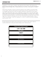
This parallel kit is meant to parallel two ParaLINK
compatible inverters together. Both inverters must
have ParaLINK parallel receptacles:
NOTICE
This unit should NOT be used to connect inverters
without ParaLINK receptacles:
NOTICE