
Operators Manual

100326-1 - 25 TON FULL BEAM LOG SPLITTER
ASSEMBLY
13
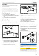
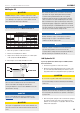
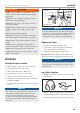
4) Install the Support Leg
Insert the support leg (60) into the leg holder on the tow bar and
secure with pin (57) and R-pin (56).
57
56
60
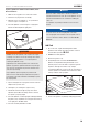
5) Install the Beam
Stand the beam (1) vertical on the foot plate.
1. Roll the tank into position so the pivot holes of the tank and
beam are aligned.
2. Insert the bolt (29) and secure it with the washers (31),
(32) and lock nut (33).
3. Tighten the lock nut (33) onto the bolt (29).
1
31
32
33
29
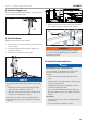
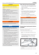
NOTICE
The bolt (29) should slide with little resistance in the slotted
hole
– When in the vertical position, the bolt should be at the
rear/bottom of the slotted hole (see Fig. A)
– When in the horizontal position, the bolt should be at the
front/top of the slotted hole (see Fig. B)
If the bolt does not slide to the correct position when the
beam is transitioned, loosen the nut in half turn increments
until it does.
FIG A
FIG B
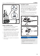
4. Pivot the beam to the horizontal position and secure it with
the lock pin (54) and R-clip (56) through the tow bar.
54
56
WARNING
The beam is extremely heavy and should only be handled
with 2 or more people. DO NOT try and lift or handle the
beam without assistance.
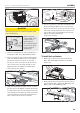
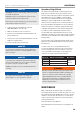
6) Install the Engine and Hoses
NOTICE
Oil Inlet (High Pressure) and Oil Return Hoses
Some hoses may be preassembled by the factory, check
your hoses per below instructions to ensure proper
assembly.
– These hoses are black and have swivel nuts on both
ends.
– The Oil Inlet Hose (19) sends hydraulic oil from the pump
to the control valve/cylinder.
– The Oil Return Hose (49) returns hydraulic oil from the
control valve/cylinder to the tank.
– Hose connections do NOT require thread seal tape. The
O-ring seals against the face of the fittings on the pump
and hose.
Suction Hose
– This is the clear hose that connects the hydraulic tank to
the pump inlet.
– Secure both ends of hose with hose clamps.