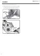
OPERATOR’S MANUAL warranty_badges.pdf 1 8/18/11 10:45 AM 50 IN. UNIVERSAL ATV SNOW PLOW SYSTEM MODEL NUMBER 100398 SAVE THESE INSTRUCTIONS Important safety instructions are included in this manual. MADE IN USA REV 100398-20170907 12039 Smith Ave. Santa Fe Springs CA 90670 USA / 1-877-338-0999 www.championpowerequipment.
Have questions or need assistance? Do not return this product to the store! WE ARE HERE TO HELP! Visit our website: www.championpowerequipment.
100398 50 IN. UNIVERSAL ATV SNOW PLOW SYSTEM TABLE OF CONTENTS Introduction. . . . . . . . . . . . . . . . . . . . . . . . Manual Conventions. . . . . . . . . . . . . . . . . . . Safety Rules. . . . . . . . . . . . . . . . . . . . . . . . Assembly. . . . . . . . . . . . . . . . . . . . . . . . . . Plow Blade Installation. . . . . . . . . . . . . . . Push Tube Assembly and Installation. . . . .
ENGLISH 100398 Introduction Congratulations on your purchase of a Champion Power Equipment (CPE) product. CPE designs, builds, and supports all of our products to strict specifications and guidelines. With proper product knowledge, safe use, and regular maintenance, this product should bring years of satisfying service.
100398 ENGLISH Manual Conventions This manual uses the following symbols to help differentiate between different kinds of information. The safety symbol is used with a key word to alert you to potential hazards in operating and owning power equipment. Follow all safety messages to avoid or reduce the risk of serious injury or death. DANGER DANGER indicates an imminently hazardous situation which, if not avoided, will result in death or serious injury.
ENGLISH 100398 Safety Rules WARNING Read this manual thoroughly before operating your snow plow. Failure to follow instructions could result in serious injury or death. WARNING –– Read this manual thoroughly before operating your plow. Failure to follow instructions could result in serious injury or death. –– Do not exceed 5 mph, even with blade raised. –– Make sure that all nuts and bolts are tightened per installation instructions.
100398 ENGLISH Assembly Plow Blade Installation Cont’d. Your snow plow requires some assembly. If you have any questions regarding the assembly of your snow plow, call our help line at 1-877-338-0999. Please have your serial number and model number available. Plow Blade Installation NOTE Before starting the assembly of the blade and tubes see Hybrid Mount installation instructions to ensure it will work with your ATV.
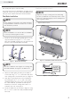
ENGLISH 100398 Assembly Push Tube Assembly and Installation Push Tube Assembly and Installation Cont’d. 1. Assemble left handle plate (12), 2× washer (15.13), pivot handle (11), right handle plate (13), and hook plate (10) using the 5⁄16 × 11⁄2 in. (7.9 × 38.1 mm) standard carriage bolt (15.4) and 5⁄16 in. (7.9 mm) flange nut (15.5) as shown in Figure 4. Tighten down nut so that angle lever moves freely. This will create the angle lever assembly (B). 4.
100398 ENGLISH Assembly Push Tube Assembly and Installation Cont’d. Push Tube Assembly and Installation Cont’d. 7. Decide desired pitch of blade. Each hole allows 5 degrees of blade pitch adjustment. 10. The tube system has five positions of rotation for your blade. Each adjustment is a 12.5 degree increment. To adjust, push down on the handle (Figure 11-A, Item 11) and rotate your blade left or right until you reach the desired angle. NOTE Figure 9 shows the default position. 8.
ENGLISH 100398 Assembly Push Tube Assembly and Installation Cont’d. 12. Attach winch hook to one of 2 locations. See Figure 13. Figure 14 shows the best winch line angle. Use this to determine which attachment point to use.
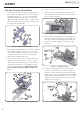
100398 ENGLISH Assembly Hybrid Mount Installation Instructions General Install Notes 1. Be sure that when installing the mount it is centered on your machine. Some frames are not perfectly centered as shown in Figure 15. General Install Noted Cont’d. CAUTION Take care when installing mount fasteners. Damage could occur to the vehicle if installed improperly. Equal Equal Round RoundTube TubeFrame Frame(Page (Page9)5) 26 in. (66 cm) 26”Approx.
ENGLISH 100398 Assembly Hybrid Mount Round Tube Frame Install 1. Place the hybrid lower mount plate up to the frame at the location behind the front tires where the frame widens out, as shown in Figure 17. Determine the location allowing the mount to be centered, back as far on the frame as possible and the push tubes to be attached. Keep the mount holes within the approximate distance from the front of your machine (see Figure 16). 2.
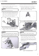
100398 ENGLISH Assembly Hybrid Mount Square Tube Frame Install 1. Check to see if the u-bolts will fit over your tube frame. If they do, it is recommended to use the u-bolts (See round tube install, Page 9). If they do not, proceed to step 2. 2. Measure the thickness of your tube frame and skid plate (if installed) see Figure 19. Then cut the provided rubber spacers to a 1⁄4 in. (6.4 mm) longer then the thickness of the tube frame. Hybrid Mount Square Tube Frame Install Cont’d.
ENGLISH 100398 Assembly Hybrid Mount Polaris ® Sportsman ® Install Hybrid Mount Polaris ® Sportsman ® Install Cont’d. 1. Measure the thickness of your tube frame and skid plate (if installed), see Figure 23. Then cut the provided rubber spacers to a 1⁄4 in. (6.4 mm) longer then the thickness of the tube frame. 5.5 5.4 2 4 3 1 2 3 4 1 FRONT Figure 23 - Frame Measurement 2. Place the upper mount plate (2) over the frame at the location behind the tires where the frame widens out.
100398 ENGLISH Specifications Blade Parts Diagram 7.2 6 5 7.5 1 7.1 2 7.3 7.4 4 3 7.2 7.2 Blade Parts List # Part Number Description 1 105526 Blade 1 2 105528 Blade Support Bracket 1 3 105158 Blade Foot 2 4 105538 Blade Reversible Wear Bar 1 5 105113 Blade Gusset RH 1 6 105114 Blade Gusset LH 1 7 HK-142 Hardware Kit 1 ⁄16-18 × 3⁄4 Carriage Bolt, Steel, Zinc Plated 4 7.1 CB-ZP-0313-18-0_75 5 Qty # Part Number 7.2 HNFN-ZP-0313-18 7.3 CB-ZP-0313-18-1_00 7.
ENGLISH 100398 Specifications Push Tube Parts Diagram 15.2 15.14 15.7 11 15.4 12 15.13 15.8 13 17 15.6 10 15.3 14 18 15.1 9 8 15.11 15.5 15.12 16 15.9 8.10 Push Tubes Parts List # Part Number Description Qty 8 105102 Tube Weldment 1 9 105087 Pivot Plate 1 10 105088 Hook Plate 1 11 105089 Pivot Handle 1 12 105094 Handle Plate LH 1 13 105099 Handle Plate RH 1 15.11 P800249 5 ⁄16”-18 × 9⁄16” × 33⁄8” Eyebolt 2 14 105214 Pitch Bushing 2 15.
100398 ENGLISH Specifications Hybrid Mount System Parts Diagram 5.1 5.5 5.4 5.3 2 4 3 1 5.2 Hyrbid Mount System Parts List # Part Number Description 1 105112 Hybrid Lower Mount Plate Weldment 1 2 105104 Hybrid Upper Mount Plate 1 3 105119 Hybrid Mount Spacer 4 4 P800335 Hybrid Rubber Mount Spacer 1.00 × 1.75 4 5 Hk-144 Hardware Kit 1 5.1 P800301 3 ⁄8”-16 × 1 ⁄2” × 2 ⁄2” × 1 ⁄4” U-Bolt 2 5.2 Hnnl-Zp-0375-16 3 ⁄8-16 Hex Nylock Nut, Steel, Zinc 5 1 Qty 1 1 5.