
Use and Care Manual


100434 - 24 IN. 2-STAGE SNOWBLOWER
ASSEMBLY
17
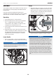
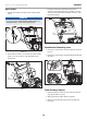
4. Tighten all nuts (10-2). Do not overtighten.
10–1
10–2
Figure 10
Snow Discharge Chute
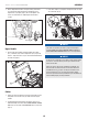
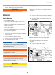
1. Remove the bolts (11-1) and nuts (11-2) on the snow
discharge chute. Set aside for next step.
2. Tighten snow discharge chute and the worm gear using three
bolts (11-1) and three nuts (11-2) (Fig. 11A).
11–2
11–1
Snow discharge chute
Component
Figure 11A
3. Remove the bolts (11-3) and nuts (11-4) on the snow
discharge support. Put the snow discharge chute on the base
of unit’s body. Attach the snow discharge support using bolts
(11-3) and nuts (11-4) (Fig. 11B).
11–3
11– 4
Figure 11B
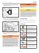
Discharge Chute Rotation Lever
1. Remove the R-clip (12-1) from the gear as applicable. Set
aside for a later step. It may be preinstalled by the factory.
2. Insert the lever through the discharge chute bracket on the
lower handle, and then into the hole of the gear (Fig. 12A).
Figure 12A
3. Align the lever and the gear, and then connect the R-clip
(12-1). (Fig. 12B).
12–1
Figure 12B