
Use and Care Manual


100434 - 24 IN. 2-STAGE SNOWBLOWER
ASSEMBLY
15
"
NOTICE
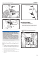
Only the left axle has two holes (Fig. 1A), and the axle pin
can be removed and repositioned. If the wheel is slid further
in on the axle with the pin inserted into the outside hole of
the axle, the machine will move freely without the engine
on (Fig. 1B). If the pin is inserted into the inside hole of the
axle, the machine will only move when the drive control is
engaged when the engine is on (Fig. 1C).
It is optional to slide one wheel past the pin hole in the
axle and to place the locking pin into the axle outside the
wheel without locking it into the drive axle. This creates a
pivot wheel that allows the operator to more easily turn the
snowblower during use by using the “free wheel” as a pivot
point. Though this makes turning easier, it decreases drive
wheel traction by 50%.
Handle
1. Attach the lower handle (2-1) onto the unit body with bolts
(2-2, 2-3) and washers (2-4) (Fig. 3). Repeat on the other
side.
2–3
2–4
2–2
2–1
Figure 3
2. Connect the upper handle and lower handle with bolts
(2-5), washers (2-6) and locking knobs (2-7) (Fig. 4).
2–5
2–7
2–6
Upper
handle
Figure 4
3. Connect discharge chute guide to lower handle with 1 bolt
(2-8), and 1 lock nut (2-9) (Fig. 5).
2–8
2–9
Discharge chute
bracket
Figure 5
"
NOTICE
Discharge chute bracket should be placed forward as shown
(for correct placement). Do not over-tighten.
Speed Control Connecting Lever
1. Connect the connecting lever (Fig. 6A) and connecting
base with cotter pin (3-1) (Fig. 6B).
2. Connect the connecting lever and speed adjusting handle
with cotter pin (3-1) (Fig. 6C).
Speed adjusting
handle
Connecting base
Speed control
connecting lever
Figure 6A