
Full Product Manual


100603 - INVERTER GENERATOR COVER DISASSEMBLING THE STRAP MOUNTING PARTS
11
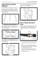
Figure 13: Find the Correct Exhaust Side Frame Rod Holes
– If the distance of the fourth hole is less than 23",
then add an Extender Arm to each side and re-
measure.
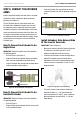
Install Remaining Extenders Onto
The Inverter Generator
IMPORTANT: Refer to Figure 14 on the next page.
– Move to the remaining two Angle Braces. The
objective is to find a span of 34" to 36" length wise,
between the rod holes on the exhaust side and the
opposite side, that also span 24" to 26" width wise.
– Install Two Extenders onto each Angle Brace.
– Position the Extender Arms at position 0 of the
Angle Brace.
– Measure the distance from one of the exhaust
side rod holes to the adjacent Extender Arm just
installed. Find the hole between 34" and 36".
– If needed, add another Extender to both dual
Extender Arm and repeat this measurement.
Make Final Extender Arm
Adjustments
Now measure the distance between the rod holes on the
two dual (or triple) Extender Arms.
– If the distance is between 23" and 25", then you
have identified the rod holes.
– If the distance is less than needed, adjust each dual
(or triple) extender arm outward on the Angle Brace
by one position and repeat this measurement.
Figure 14: Locate Remaining Extender Rod Holes
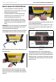
DISASSEMBLING THE STRAP
MOUNTING PARTS
Removing Extender Arms
– Extender Arms are easily removed for disassembly.
This procedure requires a small flat blade
screwdriver or similar.
– Put the flat blade in the removal slot on the top
or bottom prong of the Extender Arm that is to be
removed.
– Twist the blade toward the tip of the prong (toward
the Extender Arm or Angle Brace from which this
part is being removed).
– This twisting motion disengages one pivot pin.
– While twisting the blade, either push down on the
Extender Arm (if the blade is in the top prong), or
lift on the Extender Arm (if the blade is in the lower
prong).
– The Extender Arm will slide out and free.