
Full Product Manual


100603 - INVERTER GENERATOR COVER FRAME IT: INSTALL STORM SHIELD FRAME ON THE ARMS
12
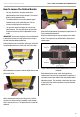
Removing Strap Mounting Assembly
From The Inverter Generator
– The Ratchet Buckle has a brass colored, spring
loaded release on the ratcheting arm. Pull and hold
this release and open the ratchet arm to its fully
open and flat.
– To loosen the strap and adjust:
– Let go of the release and close the ratchet arm
about halfway. The strap should loosen slightly.
Repeat as necessary so that adjustments can
be made.
– To completely remove the strap:
– The fixed side of the Ratchet Buckle also has a
spring-loaded release. Pull and hold this release
and the Kevlar strap can be pulled all the way
out.
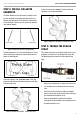
FRAME IT: INSTALL STORM
SHIELD FRAME ON THE ARMS
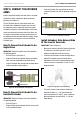
IMPORTANT NOTE: Position Central Connector with
central pin facing upward (Figure 15).
– Orient Central Connector so that short sides align
with the side of the Extender rod holes that are
the shortest apart, and the long sides align with
the Extender rod holes that are the longest apart,
respectively.
NOTICE
Each frame rod goes into the Central Connector
hole first and then into the corresponding Extender
Arm rod hole.
– Insert a fiberglass frame rod into Central Connector
hole until it stops (figure. 13).
– Insert other end of the fiberglass rod fully into the
correct Extender Arm rod hole of the corresponding
arm.
– Insert second fiberglass rod fully into the diagonally
opposite hole in the Central Connector so that the
two rods and central connector make a straight line.
– Grasping the end of this fiberglass rod, bend toward
the opposite side Extender Arm rod hole and insert
fully into the correct hole.
CAUTION
Hold rod with two hands; Fiberglass rod will be
under tension, do not release!
– Repeat for final two fiberglass rods.
– Recheck the mounting assembly. The Angle Braces
should remain firmly in place and the Extender
Arms may exhibit a slight upward lean.
– The Extender Arm assemblies at each corner should
be in a straight line. If any are exhibiting an arc,
move the Extender Arm one position in the direction
of the arc on the Angle brace, or alternatively move
the entire Angle Brace in the direction of the arc
until the Extender Arms straighten out.
Figure 15: Center Connector with Center Pin Facing Upward