41111 Rev 41111-20090414 10006 Santa Fe Springs Road Santa Fe Springs, CA 90670 USA Made in China Owner’s Manual and Operating Instructions SAVE THESE INSTRUCTIONS Important Safety Instructions are included in this manual 6000 Peak Watts / 5000 Running Watts PORTABLE GENERATOR
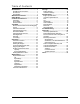
Table of Contents Introduction ..................................... 1 Portable Power Generator ........................ 1 Accessories................................................ 1 This Booklet .............................................. 1 Manual Conventions ......................... 2 Safety Rules ...................................... 3 Controls and Features ....................... 5 Generator .................................................. 5 Power Panel .........................................
Introduction Introduction Accessories Congratulations on your purchase of a Champion Power Equipment generator. CPE designs and builds generators to strict specifications. With proper use and maintenance, this generator will bring years of satisfying service. This Owner’s Manual contains important safety instructions and information. SAVE THESE INSTRUCTIONS FOR FUTURE REFERENCE. Portable Power Generator This unit is a gasoline engine driven, alternating current (AC) generator.
Manual Conventions Manual Conventions CAUTION This manual uses the following symbols to help differentiate between different kinds of information. The safety symbol is used with a key word to alert you to potential hazards in operating and owning power equipment. CAUTION indicates a potentially hazardous situation which, if not avoided, may result in minor or moderate injury. Follow all safety messages to avoid or reduce the risk of serious injury or death.
Safety Rules Safety Rules WARNING Read this manual thoroughly before operating your generator. Failure to follow instructions could result in serious injury or death. WARNING The engine exhaust from this product contains chemicals known to the state of California to cause cancer, birth defects, or other reproductive harm. DANGER Generator exhaust contains carbon monoxide, a colorless, odorless, poison gas. Breathing carbon monoxide will cause nausea, dizziness, fainting or death.
Safety Rules A spark arrestor may be required. the operator should contact local fire agencies for laws or regulations relating to fire prevention requirements. DANGER Fuel and fuel vapors are highly flammable and extremely explosive. Fire or explosion can cause severe burns or death. Unintentional startup can result in entanglement, traumatic amputation or laceration. When adding or removing fuel Turn the generator off and let it cool for at least two minutes before removing the fuel cap.
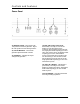
Controls and Features Controls and Features Read this owner’s manual before operating your generator. Familiarize yourself with the location and function of the controls and features. Save this manual for future reference. Generator (1) Fuel Tank – 6.5 gallon capacity fuel tank. (2) Fuel Valve – Turn this valve to the “On” position to supply fuel to the engine. (3) Choke Lever – Used to start the engine. (4) Air Cleaner – Protects the engine by filtering dust and debris from the intake air.
Controls and Features Power Panel (1) Ignition Switch – Flip switch to the “On” position to start the generator. Flip to the “Off” position to turn off the generator. (2) Circuit Breakers – Protects the generator against electrical overload. (3) Voltmeter – Displays the output voltage of the generator. (4) 120 /240 V 30 A Twist-Lock – Protected by a 25 A flip-to-reset circuit breaker on each 120 Volt leg of the receptacle.
Controls and Features Parts Included Your Model 41111 Gasoline Powered Generator ships with the following parts: Rev 41111-20090414 Wheel Kit Handle Assembly 8” Solid Wheel Axle Assembly Support Leg Vibration Mounts Support Leg Hardware 1 set 2 piece 2 sets 1 piece 2 piece 1 set Oil Funnel Spark Plug Socket 1 piece 1 piece Spark Arrester Kit Spark Arrester Cover Plate Screws, Lock Washers 1 piece 1 piece 2 pieces 7
Assembly Assembly Your generator requires some assembly. This unit ships from our factory without oil. It must be properly serviced with fuel and oil before operation. If you have any questions regarding the assembly of your generator, call our help line at 1-877-338-0999. Please have your serial number and model number available. Install the Support Leg 1. Remove the Generator from the Shipping Carton Attach the rubber vibration mount to the support leg with a cap screw (M8x25) and lock nut (M8). 1.
Assembly 2. Remove oil fill cap/dipstick to add oil. Install the Spark Arrester Insert the spark arrester screen into the muffler outlet. Secure the spark arrester by placing the cover plate over the end of the screen, with the lettering facing outward. Secure the cover plate with the two screws and lock washers provided with the spark arrester kit. NOTE Federal and local laws and administrative requirements indicate when and where spark arresters are required.
Assembly Grounding Your generator must be properly connected to an appropriate ground to help prevent electric shock. WARNING 6. Screw on the fuel cap and wipe away any spilled fuel. CAUTION Use regular unleaded gasoline with a minimum octane rating of 85. DO NOT mix oil and gasoline. Fill tank to approximately ¼” below the top of the tank to allow for fuel expansion. DO NOT fill fuel tank indoors. DO NOT fill fuel tank when the engine is running or hot. DO NOT overfill the fuel tank.
Operation Operation Generator Location Please consult your local authority. In some areas, generators must be registered with the local utility. Generators used at construction sites may be subject to additional rules and regulations. This generator must have at least five feet of clearance from combustible material. Leave at least three feet of clearance on all sides of the generator to allow for adequate cooling, maintenance and servicing. Place the generator in a well-ventilated area.
Operation Do Not Overload Generator Capacity Follow these simple steps to calculate the running and starting watts necessary for your purposes. 1. Select the electrical devices you plan on running at the same time. 2. Total the running watts of these items. This is the amount of power you need to keep your items running. 3. Identify the highest starting wattage of all devices identified in step 1. Add this number to the number calculated in step 2.
Maintenance Maintenance 6. Dispose of used oil at an approved waste management facility. The owner/operator is responsible for all periodic maintenance. WARNING Never operate a damaged or defective generator. Spark Plugs WARNING Tampering with the factory set governor will void your warranty. 1. Remove the spark plug cable from the spark plug. 2. Use the spark plug tool that shipped with your generator to remove the plug. 3. Inspect the electrode on the plug.
Maintenance Air Filter 1. 2. 3. 4. 5. 6. 7. Remove the snap-on cover holding the air filter to the assembly. Remove the foam element. Wash in liquid detergent and water. Squeeze thoroughly dry in a clean cloth. Saturate in clean engine oil. Squeeze in a clean, absorbent cloth to remove all excess oil. Place the filter in the assembly. Reattach the air filter cover and snap in place. Spark Arrester 1. 2. 3. 4. 5. 6. Allow the engine to cool completely before servicing the spark arrester.
Maintenance Water can enter the generator through the cooling slots and damage the generator windings. Use a damp cloth to clean exterior surfaces of the generator. Rev 41111-20090414 Use a soft bristle brush to remove dirt and oil. Use an air compressor (25 PSI) to clear dirt and debris from the generator. Inspect all air vents and cooling slots to ensure that they are clean and unobstructed.
Storage Storage The generator should be started at least once every 14 days and allowed to run for at least 20 minutes. For longer term storage, please follow these guidelines. 5. Change the oil. 6. Remove the spark plug and pour about ½ ounce of oil into the cylinder. Crank the engine slowly to distribute the oil and lubricate the cylinder. 7. Reattach the spark plug. Generator Storage Engine Storage 1. Allow the engine to cool completely before storage. 2.
Specifications Specifications Engine Specifications Engine 337 cc OHV CPE Generator Specifications Running Wattage Starting Wattage AC Load Phase Frequency Fuel Capacity Weight Height Width Length 5000 Watts 6000 Watts 120/240 V Single 60 Hz 6.5 gallons (25 L) 170.9 lbs. (77.5 kg) 24.2 inches (61.5 cm) 26.2 inches (66.5 cm) 30.
Specifications Parts Diagram 18 Rev 41111-20090414
Specifications Parts List Item 1 2 3 4 5 6 7 8 9 10 11 12 13 14 15 16 17 18 19 20 21 22 23 24 25 26 27 28 29 30 31 32 33 34 35 36 37 38 39 40 41 42 43 44 45 46 47 48 49 50 51 Part Number ST02FD-1151205A ST05FD-05017600 ST05FD-1151202-25A ST05FD-1151202-20A ST02FD-05602010-D ST02FD-05502022 ST02FD-05502023 GB5781-B6-22 GB90-W-6 GB93-LW-6 GB41-N-6 GB5789-FB6-12 ST05FD-05205009 ST05FD-05215003 ST05FD-05215009 ST05FD-05215001 GB5789-FB5-12 ST05FD-1152002 GB5789-FB5-16 ST168FD-1150230 ST05F-1152031A ST02FD-1152
Specifications Item 52 53 54 55 56 57 58 59 60 61 62 63 64 65 66 67 68 69 70 71 72 73 74 75 76 77 78 79 80 81 82 83 84 85 86 87 88 89 90 91 92 20 Part Number GB90-W-6 ST168FD-1163000 ST188FD-1100001-G ST188FD-1100100-G GB5789-FB8-25 ST188FD-1090006 GB41-N-6 GB90-W-8 GB93-LW-8 GB41-N-8 ST188FD-1101300-A ST188FD-1100105 ST188FD-1100104 ST188FD-1180121 ST188FD-1100010-88 GB5789-FB5-14 GB93-LW-5 ST188FD-1100103 GB5789-FB8-20 ST188FD-1100006 GB5789-FB8-20 GB90-W-6 GB93-LW-6 2910 GB1667-S5-12 GB1667-S4-12 GB41-
Specifications Wiring Diagram 21
Troubleshooting Troubleshooting Problem Generator will not start Generator will not start or generator starts but runs roughly Generator shuts down during operation Generator cannot supply enough power or overheating Cause No fuel Faulty spark plug Unit loaded during start up Low oil level Choke in the wrong position Spark plug wire loose Out of fuel Low oil level Generator is overloaded Insufficient ventilation No AC output Cable not properly connected Connected device is defective Circuit breaker is
Warranty Warranty CHAMPION POWER EQUIPMENT 1 YEAR LIMITED WARRANTY Effective September 1, 2006. Replaces all undated warranties and all warranties dated before September 1, 2006. Warranty Qualifications Champion Power Equipment (CPE) will register this warranty upon receipt of your Warranty Registration Card and a copy of your sales receipt from one of CPE's retail locations as proof of purchase.
Warranty Champion Power Equipment, Inc (CPE), and the United States Environment Protection Agency (U.S. EPA.) Emission Control System Warranty Your Champion Power Equipment (CPE) engine complies with U.S. EPA emission regulations. YOUR WARRANTY RIGHTS AND OBLIGATIONS: The US EPA AND CPE are pleased to explain the Federal Emission Control Systems Warranty on your 2009 small off-road engine. New engines must be designed, built and equipped, at the time of sale, to meet U.S.
Warranty EMISSION CONTROL SYSTEM WARRANTY The following are specific provisions relative to your Emission Control System Warranty Coverage. Emission Control System Warranty (ECS Warranty) for 1997 and later model year California small off-road engines (for other states, 1997 and later model year engines): 1. APPLICABILITY: This warranty shall apply to 1997 and later model year engines).
Warranty ECS Warranty claim. CPE shall not be liable hereunder for failures of any warranted parts of a CPE engine caused by the use of such an unapproved add-on or modified part.
Notes Notes Rev 41111-20090414 27