80002 Rev 80002-20080228 10006 Santa Fe Springs Road Santa Fe Springs, CA 90670 USA Made in China Owner’s Manual and Operating Instructions 60-90A MIG WELDER
Table of Contents Introduction ..................................... 1 Portable Welder ........................................ 1 This Booklet .............................................. 1 Manual Conventions ......................... 2 Safety Rules ...................................... 3 Controls and Features ....................... 4 MIG/Flux Welder ..................................... 4 Parts Included .......................................... 5 Assembly ..........................................
Introduction Introduction This Booklet Congratulations on your purchase of a Champion Power Equipment portable welder. CPE designs and builds welders to strict specifications. With proper use and maintenance, this welder will bring years of satisfying service. Every effort has been made to ensure the accuracy and completeness of the information in this manual. We reserve the right to change, alter and/or improve the product and this document at any time without prior notice.
Manual Conventions Manual Conventions CAUTION This manual uses the following symbols to help differentiate between different kinds of information. The safety symbol is used with a key word to alert you to potential hazards in operating and owning power equipment. CAUTION indicates a potentially hazardous situation which, if not avoided, may result in minor or moderate injury. Follow all safety messages to avoid or reduce the risk of serious injury or death.
Safety Rules Safety Rules DANGER ARC rays can burn eyes and skin. WARNING Read this manual thoroughly before operating your welder. Failure to follow instructions could result in serious injury or death. DANGER Breathing welding fumes can be hazardous to your health Keep head and face away from welding fumes. Use enough ventilation to avoid the buildup of gas and fumes in the immediate area. Do not breathe in fumes. Use of a ventilating fan may be necessary.
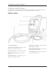
Controls and Features Controls and Features Read this owner’s manual before operating your welder. Familiarize yourself with the location and function of the controls and features. Save this manual for future reference. MIG/Flux Welder Carrying handle (1) Thermal Overload indicator (2) – Allow welder to cool, reduce duty cycle. On/Off switch (3) – Power On, Power Off. MIG Welding Gun (4) – Wire fed torch handle. Amperage control (6) – Dial adjustment, from 26amps to 90amps.
Controls and Features Parts Included Your 8000 ARC Welding unit ships with the following parts: Handheld Welding Mask Wire Brush/Slag Hammer Torch Nozzle(1) Wire Feed Roller (.6 dia. And .8 dia.
Assembly Assembly Your welder requires some assembly. If you have any questions regarding the assembly of your welder, call our help line at 1-877-338-0999. Please have your serial number and model number available. This unit can be used for MIG/MAG (CO2 gas-protected) welding or Flux wire (nongas) welding. This unit does not include equipment for gas-protected uses (CO2 gas cylinder, pressure gauges, hoses, etc.) Installing Wire Feed This unit supports wire sizes of .6mm, .8mm, .
Assembly NOTE If the wire does not feed, view the Wire Feed Unit and see if the wire is being pushed. If it is not, turn the welder OFF and add more tension to the Wire Feed Adjusting Spring. 13. Turn the welder on again and press the trigger. 14. Once the wire is exposed, turn the welder OFF. 15. Slide the Contact Tip over the wire and screw it into the Torch Handle. 16. Replace the Nozzle and cut off any excess wire over 2 inches 17.
Operation Operation Welder Location Place on a flat surface free of vibration. This unit may be placed on a certified welding cart (not included) and can be set at an angle of 10 degrees. Place the welder in a well-ventilated area. DO NOT place the welder near vents or intakes where exhaust fumes could be drawn into occupied or confined spaces. Carefully consider wind and air currents when positioning welder. Place the welder in a clean, dry place.
Maintenance and Storage Maintenance The owner/operator is responsible for all periodic maintenance. WARNING Never operate a damaged or defective welder. WARNING Use a soft bristle brush to remove dirt. Use an air compressor (25 PSI) to clear dirt and debris from the welder. Inspect all air vents and cooling slots to ensure that they are clean and unobstructed. Every 3 months Repair or replace cracked cables Every 6 months Vacuum or blow out inside.
Specifications Specifications Rated Input Voltage Phase Frequency Current 80002 120V 1 60Hz 20A Duty Cycle and Overheating Duty Cycle is a percentage of 10 minutes that the unit can weld at a given rated load without overheating. For example a 20% duty cycle means 2 minutes welding, 8 minutes resting. If unit overheats, wait 15 minutes for unit to cool, reduce amperage or duty cycle when welding resumes. Rated Output Duty Cycle Voltage 10 90A (max) 20% 18.5V 66A 35% 17.3V 50A 60% 16.5V 26A 100% 15.
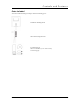
Specifications Parts Diagram 11
Specifications Parts List Item# 1 2 3 4 5 6 7 8 9 10 11 12 13 14 15 16 17 18 19 20 21 22 23 24 25 26 27 28 29 30 31 32 33 34 35 36 37 38 39 40 41 42 43 44 45 46 47 48 49 50 51 52 53 54 12 Part # Description Qty 80002-01 80002-02 80002-03 80002-04 80002-05 80002-06 80002-07 80002-08 80002-09 80002-10 80002-11 80002-12 80002-13 80002-14 80002-15 80002-16 80002-17 80002-18 80002-19 80002-20 80002-21 80002-22 80002-23 80002-24 80002-25 80002-26 80002-27 80002-28 80002-29 80002-30 80002-31 80002-32 80002-33
Specifications Item# 55 56 57 58 59 60 61 62 63 64 65 66 67 68 69 70 71 72 73 74 75 76 77 78 79 80 81 82 83 84 85 86 87 88 89 90 Part # Description Qty 80002-55 80002-56 80002-57 80002-58 80002-59 80002-60 80002-61 80002-62 80002-63 80002-64 80002-65 80002-66 80002-67 80002-68 80002-69 80002-70 80002-71 80002-72 80002-73 80002-74 80002-75 80002-76 80002-77 80002-78 80002-79 80002-80 80002-81 80002-82 80002-83 80002-84 80002-85 80002-86 80002-87 80002-88 80002-89 80002-90 Shaft Support, PA66 Feed Roller
Troubleshooting Troubleshooting Problem No weld output and fan is not running Weld output but fan does not run Erratic weld current Erratic arc with excessive spatter Electrode wire feeding stops during welding Cause Power switch is OFF Fuse overload Blocked fan movement Loose cable connections Poor, damaged electrodes Long arc length High amperage setting Gun cable/Gun malfunction Poor drive roll pressure Defective contact tip Restricted drive assembly 14 Solution Switch ON Reset breakers if necessary
Warranty Warranty CHAMPION POWER EQUIPMENT 1 YEAR LIMITED WARRANTY Effective September 1, 2006. Replaces all undated warranties and all warranties dated before September 1, 2006. Warranty Qualifications Champion Power Equipment (CPE) will register this warranty upon receipt of your Warranty Registration Card and a copy of your sales receipt from one of CPE's retail locations as proof of purchase.
Notes Notes 16 Rev 80002-20080228