OWNER’S MANUAL & OPERATING INSTRUCTIONS 2000 Max Watts / 1600 Rated Watts PORTABLE INVERTER GENERATOR MODEL NUMBER 73535i US Patent # D656897, 8391012 SAVE ThESE INSTRUCTIONS Important Safety Instructions are included in this manual. MADE IN CHINA REV 73535i-20130307 10006 Santa Fe Springs Road Santa Fe Springs CA 90670 USA 1-877-338-0999 www.championpowerequipment.
AN IMPORTANT MESSAGE ABOUT TEMPERATURE: Your Champion Power Equipment product is designed and rated for continuous operation at ambient temperatures up to 40°C (104°F). When your product is needed your product may be operated at temperatures ranging from -15°C (5°F) to 50°C (122°F) for short periods. If the product is exposed to temperatures outside this range during storage, it should be brought back within this range before operation.
73535i 2000 Max Watts / 1600 Rated Watts PORTABLE INVERTER GENERATOR Table of Contents Introduction. . . . . . . . . . . . . . . . . . . . . . . . . . . . . 1 Introduction. . . . . . . . . . . . . . . . . . . . . . . . . . . 1 Portable Power Generator. . . . . . . . . . . . . . . . . . 1 Accessories . . . . . . . . . . . . . . . . . . . . . . . . . . . 1 This Booklet. . . . . . . . . . . . . . . . . . . . . . . . . . . 1 Manual Conventions. . . . . . . . . . . . . . . . . . . . . . . . 2 Safety Rules. . .
ENGLISH 73535i Introduction Introduction Accessories Congratulations on your purchase of a Champion Power Equipment inverter generator. CPE designs and builds generators to strict specifications. With proper use and maintenance, this generator will bring years of satisfying service. Champion Power Equipment manufactures and sells accessories designed to help you get the most from your purchase. To find out more about our covers and power cables, please visit our web site at: www.championpowerequipment.
73535i ENGLISH Manual Conventions This manual uses the following symbols to help differentiate between different kinds of information. The safety symbol is used with a key word to alert you to potential hazards in operating and owning power equipment. Follow all safety messages to avoid or reduce the risk of serious injury or death. DANGER DANGER indicates an imminently hazardous situation which, if not avoided, will result in death or serious injury.
ENGLISH 73535i Safety Rules WARNING Read this manual thoroughly before operating your generator. Failure to follow instructions could result in serious injury or death. WARNING The engine exhaust from this product contains chemicals known to the state of California to cause cancer, birth defects, or other reproductive harm. DANGER Generator exhaust contains carbon monoxide, a colourless, odourless, poison gas. Breathing carbon monoxide will cause nausea, dizziness, fainting or death.
3535i ENGLISH DANGER Safety Rules WARNING Fuel and fuel vapours are highly flammable and extremely explosive. Fire or explosion can cause severe burns or death. Unintentional startup can result in entanglement, traumatic amputation or laceration. Rapid retraction of the starter cord will pull hand and arm towards the engine faster than you can let go. Unintentional startup can result in entanglement, traumatic amputation or laceration. Broken bones, fractures, bruises or sprains could result.
ENGLISH 73535i Controls and Features Read this owner’s manual before operating your generator. Familiarize yourself with the location and function of the controls and features. Save this manual for future reference. Inverter 1 2 3 5 7 4 6 5 (1) Carrying Handle (5) Spark Plug Access Cap (2) Fuel Lever Vent – Turn this valve to the “On” position to supply air to the tank. (6) Maintenance Cover – Oil filler, Air filter, and Carburetor access. (3) Fuel Cap – Remove to add fuel.
73535i ENGLISH Controls and Features Power Panel 1 2 3 4 6 5 7 10 8 (1) Oil Warning Light – Check oil level when this light turns on. Engine will not run when indicator is lit. (2) Overload Indicator Light – This light turns ON when the generator is overloaded and will cut power to the receptacles. (3) Output Light – Remains ON during normal operating conditions. Shuts OFF when generator is overloaded.
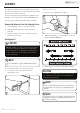
ENGLISH 73535i Assembly Your generator requires some assembly. This unit ships from our factory without oil. It must be properly serviced with fuel and oil before operation. If you have any questions regarding the assembly of your generator, call our help line at 1-877-338-0999. Please have your serial number and model number available. Add Engine Oil Cont’d. 3. Remove oil fill cap/dipstick to add oil. Remove the Generator from the Shipping Carton 1. Set the shipping carton on a solid, flat surface. 2.
73535i ENGLISH Add Fuel 1. 2. 3. 4. 5. 6. Use clean, fresh, regular unleaded fuel with a minimum octane rating of 85 and an ethanol content of less than 10% by volume. DO NOT mix oil with fuel. Clean the area around the fuel cap. Remove the fuel cap. Slowly add fuel to the tank. DO NOT OVERFILL. Fuel can expand after filling. A minimum of 6.4 mm (¼ in.) of space left in the tank is required for fuel expansion, more than 6.4 mm (¼ in.) is recommended.
ENGLISH 73535i Operation Generator Location Grounding NEVER operate the generator inside any building, including garages, basements, crawlspaces and sheds, enclosure or compartment, including the generator compartment of a recreational vehicle. Please consult your local authority. In some areas, generators must be registered with the local utility. Generators used at construction sites may be subject to additional rules and regulations. Generators should be on a flat, level surface at all times.
73535i ENGLISH Operation Starting the Engine Cont’d. Connecting Electrical Loads 6. 1. Turn the engine switch to the “On” position. 2. –– –– –– Let the engine stabilize and warm up for a few minutes after starting Plug in and turn on the desired 120 Volt AC single phase, 60 Hz electrical loads. DO NOT connect 3-phase loads to the generator. DO NOT connect 50 Hz loads to the generator. DO NOT overload the generator. NOTE 7.
ENGLISH 73535i Operation Stopping the Engine 1. Turn off and unplug all electrical loads. Never start or stop the generator with electrical devices plugged in or turned on. 2. Let the generator run at no-load for several minutes to stabilize internal temperatures of the engine and generator. 3. Turn the Fuel Valve to the “OFF” position. 4. Let the engine run until fuel starvation has stopped the engine. This usually takes a few minutes. 5. Turn the engine switch to the “Off” position. 6.
73535i ENGLISH The owner/operator is responsible for all periodic maintenance. MAINTENANCE AND STORAGE Oil Cont’d. WARNING Never operate a damaged or defective generator. WARNING Tampering with the factory set governor will void your warranty. Spark Plugs WARNING Improper maintenance will void your warranty. NOTE Maintenance, replacement, or repair of emission control devices and systems may be performed by any non-road engine repair establishment or individual.
ENGLISH 73535i Maintenance and Storage Air Filter Spark Arrester Cleaning 1. 2. 3. 4. 1. 2. 3. 4. 5. 6. 7. 8. 9. Remove the maintenance cover. Locate the air filter plastic cover. Remove the screw using a Phillips head screwdriver. Remove the foam element. Wash in liquid detergent and water. Squeeze thoroughly dry in a clean cloth. Saturate in clean engine oil. Squeeze in a clean, absorbent cloth to remove all excess oil. Place the filter in the assembly. Reattach the air filter cover.
73535i ENGLISH Maintenance and Storage Maintenance Schedule Storage Follow the service intervals indicated in the following maintenance schedule. Service your generator more frequently when operating in adverse conditions. Contact our help line at 1-877-338-0999 to locate the nearest Champion Power Equipment certified service dealer for your generator or engine maintenance needs. The generator should be started at least once every 14 days and allowed to run for at least 20 minutes.
ENGLISH 73535i Specifications US Patent # D656897, 8391012 Engine Specifications –– –– –– –– Model. . . . . . . . . . . . . . . . . . . . . . . YF149FD-330 Displacement. . . . . . . . . . . . . . . . . . . . . . . . 80cc Type. . . . . . . . . . . . . . . . . . . . . . . . 4-Stroke OHV Start Type . . . . . . . . . . . . . . . . . . . . . . . . . Recoil Generator Specifications –– –– –– –– –– –– –– –– –– –– –– –– Model. . . . . . . . . . . . . . . . . . . . . . . . . . . 73535i Rated Load . . . . . . .
Specifications 73535i ENGLISH Wiring Diagram GENERATOR DC COIL AC COIL SUB COIL G G IGNITION COIL B BLACK Br BROWN Y YELLOW B/W BLACK WHITE L BLUE W/G WHITE GREEN G GREEN G/Y GREEN YELLOW RED R W/L WHITE BLUE W WHITE O ORANGE C CARNATION A AMETHYST G G L G/Y R R R Y Y PARALLEL POWER UNIT R B PARALLEL R B Y G OPERATION CONTROL R B G Y O Y L C SPARKING PLUG CONTROL UNIT STEPPING MOTOR R W B L C B/W W O 14A TCI UNIT PARALLEL TERMINAL R CIRCUIT BREAKER W ECO.SW STOP.
17 31 32 33 REV 73535i-20130307 25 30 28 27 26 29 39 40 37 44 32 1 19 63 62 15 2 43 1 63 62 18 45 46 5 21 20 24 23 22 36 37 35 38 41 2 42 17 16 17 34 59 58 8 68 61 60 14 66 47 48 49 9 8 67 64 13 12 10 11 50 7 6 65 10 2 51 45 57 1 5 4 52 62 63 53 55 56 63 62 54 3 2 1 Specifications ENGLISH 73535i Parts Diagram
73535i ENGLISH Parts List # Part Number Description Qty # Part Number Description 1 81.200800.00.2 Crossbanding 4 33 5.1130.001 Receptacle 1 2 1.818.0514.3 Screw M5×14 17 34 81.210200.00 Toroid Coil,Comp. 1 3 81.200300.00.48 Cover, Right Side 1 35 1.97.1.04.3 WasherΦ4 3 4 2.02.014 Nut M6 4 36 81.130200.00 Pull Choke Assembly 1 5 2.02.010 Nut M5 7 37 1.818.0412.3 Screw M4×12 3 6 81.200601.00.2 Base Setting Comp. 1 38 81.070001.00 Fuel Knob 1 7 81.
19 REV 73535i-20130307 28 27 26 13 25 24 29 30 1 48 32 50 23 22 21 89 1 31 49 20 51 19 54 55 56 12 11 10 9 43 44 45 46 47 53 13 38 39 40 41 42 52 18 17 16 15 14 13 88 90 1 36 37 33 34 35 106 8 7 63 6 64 19 65 66 57 5 67 62 47 58 69 4 3 68 61 60 59 2 1 70 71 72 104 58 70 78 79 80 81 82 83 84 85 3 86 87 96 95 93 94 92 91 73 74 75 76 77 105 97 98 99 100 101 102 103 13 Specifications ENGLISH 73535i Engine Parts Diagram
73535i ENGLISH Engine Parts List # Part Number Description 1 1.5789.0612 Flange Bolt M6x12 2 81.061000.00 Recoil Assy. Qty # Part Number Description Qty 10 54 81.081100.00 Muff. Protector, Side 1 1 55 81.081003.00 Fastening Insert 1 81.081001.00 Muff. Protector Seal 1 3 1.5789.0615 Flange Bolt M6x15 5 56 4 2.02.013 Nut 1 57 81.080003.00 Air Duct 1 5 81.080100.00 Fan Cover 1 58 1.6177.1.06.3 Flange Nut M6 6 6 2.02.018 Nut M12X1.25 2 59 81.020001.
ENGLISH 73535i Troubleshooting Problem Cause Solution Generator will not start No fuel Add fuel Faulty spark plug Replace spark plug Unit loaded during start up Remove load from unit Low oil level Fill crankcase to the proper level Generator will not start; Generator starts but runs roughly Generator shuts down during operation Generator cannot supply enough power or overheating No AC output Repeated circuit breaker tripping Place generator on a flat, level surface Choke in the wrong posit
73535i ENGLISH Warranty WARRANTY CHAMPION POWER EQUIPMENT 2 YEAR LIMITED WARRANTY Warranty Qualifications Champion Power Equipment (CPE) will register this warranty upon receipt of your Warranty Registration Card and a copy of your sales receipt from one of CPE’s retail locations as proof of purchase. Please submit your warranty registration and your proof of purchase within ten (10) days of the date of purchase.
Champion Power Equipment, Inc (CPE), Emission Control System Warranty Your Champion Power Equipment (CPE) engine complies with Environment Canada (EC) emission regulations. YOUR WARRANTY RIGHTS AND OBLIGATIONS: CPE is pleased to explain the Emission Control Systems Warranty on your 2013 small off-road engine. New engines must be designed, built and equipped, at the time of sale, to meet EC regulations for small non-road engines.
EMISSION CONTROL SYSTEM WARRANTY The following are specific provisions relative to your Emission Control System Warranty Coverage. Emission Control System Warranty (ECS Warranty): 1. APPLICABILITY: The ECS Warranty Period shall begin on the date the new engine or equipment is delivered to its original, end-use purchaser, and shall continue for 24 consecutive months thereafter. 2.
EMISSION-RELATED PARTS INCLUDE THE FOLLOWING: (using those portions of the list applicable to the engine) Systems covered by this warranty Fuel Metering System Air Induction System Ignition System Exhaust System Miscellaneous Parts Parts Description Fuel regulator, Carburetor and internal parts Air cleaner, Intake manifold Spark plug and parts, Magneto ignition system Exhaust manifold, catalytic converter Tubing, Fittings, Seals, Gaskets, and Clamps associated with these listed systems.