Technical Manual Taskmaster Power Wash Sink System Model PP-3 Machine Serial No. P.O. Box 4149 Winston Salem, NC 27115-4149 336/661-1556 Fax:: 336/661-1660 2674 N. Service Road Jordan Station, Ontario, Canada L0R 1S0 905/562-4195 Fax: 905/562-4618 www.championindustries.
This Page Intentionally Left Blank
USER MANUAL Operation & Installation Guide Champion Industries PO Box 4149 Winston Salem, NC 27115 336/661-1556 www.championindustries.
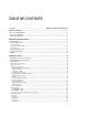
TABLE OF CONTENTS NOTES....................................................................................... ERROR! BOOKMARK NOT DEFINED. INITIAL START UP........................................................................................................................... 6 FILL TANKS WITH WATER ................................................................................................................... 6 ADD SOAP / CHEMICALS .....................................................................
AL2 State....................................................................................................................................................24 Trouble Shooting........................................................................................................................... 25 DELUXE CONTROL CENTER ............................................................................................................ 26 Display ..................................................................
Wire Diagrams.............................................................................................................................. 43 DELUXE – 208V w/Communications .......................................................................................................43 DELUXE – 480V w/Communications .......................................................................................................43 DELUXE – 480V w/Communications ................................................................
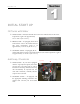
S T A R T U P INITIAL START UP Fill Tanks with Water ¾ WASH TANK – Fill wash tank with hot water to the marked Fill Line. The water temperature ought to be approximately 110˚ to 120˚ F (43˚ to 49˚ C). ¾ RINSE TANK – If equipped, fill the rinse tank with hot water to the marked Fill Line. The water temperature ought to be approximately 75˚ to 80˚ F (24˚ to 27˚ C). ¾ SANITIZE TANK – If equipped, fill the sanitize tank with hot water to the marked Fill Line.
S T A R T U P Approved Chemicals It is recommended that chemicals that are low to non foaming, metal safe, and noncaustic be used in the wash and sanitize tank. Caustic chemicals are capable of burning, corroding, or destroying living tissue and should not be used. If you plan on using caustic chemicals, then a rolling lid is required. If your unit did not come with a rolling lid, one can be ordered from the factory. Contact information is provided on the inside cover of this manual.
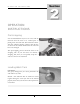
O P E R A T I O N I N S T R U C T I O N S OPERATION INSTRUCTIONS Pre-Scrapping It is recommended that any loose or excess soils be removed from the item to be washed prior to placing it into the wash tank. This will ensure a faster and more efficient cleaning operation and will also cut down on the number of times that the water will have to be changed. This pre-scrapping process should be done in the scrapping sink.
O P E R A T I O N I N S T R U C T I O N S Utensils and Silver Ware Utensils and Silver Ware must be placed in a utensil basket. If your unit was not supplied with a utensil basket, one can be ordered from the factory. Contact information is provided on the inside cover of this manual. To use the utensil basket, simply hang the basket over the side of the wash tank, place the utensils and silver ware in the basket, and run a wash cycle. WARNING – Never load sharp objects or silver ware into the machine.
O P E R A T I O N I N S T R U C T I O N S Unload Wash Tank The display will indicate that the items are clean when a wash cycle has been completed. At this time the system will switch to a holding cycle. This cycle has slower water movement that will keep grease and soiled sediments from falling back onto the items that were just cleaned. Remove the clean items from the wash tank and dip into the rinse tank to rinse off any soap or soiled residue. Place items into the sanitize tank.
O P E R A T I O N I N S T R U C T I O N S NOTES 11
C O N T R O L P A N E L S Control Panels Identifying your control panel There are two types of control panels used, the STANDARD and the DELUXE. Your control box type is printed on the front cover. Use the diagrams below to determine which control box you have.
C O N T R O L P A N E L S STANDARD Control Center 115 Mylar Buttons ¾ Temp Button, press to set or display the wash tanks running temperature. When pressed, the display will toggle between sp and 115 (115 represents a temperature set point value and may be different from your display), at this time you can press the Up and Down Arrow keys to change the set point temperature. Once changed, press the Temp button again to lock in the new value.
C O N T R O L P A N E L S Mylar Indicator Lights The heater light will illuminate whenever the wash tank’s heater is powered on. The alarm light will illuminate whenever an alarm has occurred. The change water indicator light will flash when it is time to change water. The display will show drn. The soap indicator light will illuminate whenever the soap pump is powered on.
C O N T R O L P A N E L S Advanced Operation Changing Temperature Set Point The temperature set point is the water temperature setting for the wash tank and is the only parameter that can be set by the operator. If the TEMP button is pressed once, the display will switch back and forth from sp and 115 (115 represents the temperature setting and may be different from your display). Use the UP or DOWN buttons to change the temperature setting. Once set, press the TEMP button to lock in the new value.
C O N T R O L P A N E L S Parameter Mnemonic Parameter Name Description Table 1 Default Value (Celsius) Table 2 Default Value (Fahrenheit) sp Setpoint Temperature Set Point 46ºc 115 ºF t Timer 1 4.00 4.00 t2 Timer 2 2.00 2.00 t3 Timer 3 Soap Dispensing Time 0.30 0.30 Al.1 Alarm 1 Alarm 1 Set Point 107 ºc 225 ºF Hs.1 Hysteresis Alarm 1 Hysteresis 0.1 0.1 Al..2 Alarm 2 Alarm 2 Set Point 72 ºc 160 ºf Alarm 2 Hysteresis 0.1 0.1 On/Off Hysteresis 0.1 0.
C O N T R O L P A N E L S Description Table 1 Default Value (Celsius) Table 2 Default Value (Fahrenheit) P1 Input table 2 10 P2 Low scale range of sensors 0 ºc 0 ºf P3 High scale range of sensors 282 ºc 540 ºf P4 Output 1 control action reu reu P5 Output 2 function 1 1 P6 Output 2 alarm type h.r. h.r. P8 Alarm 1 standby function Off Off P11 Auto-ranging display Off Off P1 2 Filter sensor values On On P22 Output 3 function 1 1 P23 Output 3 alarm type h.r. h.r.
C O N T R O L P A N E L S Display Software Version To display the software version, enter the configuration mode (See instructions listed in the Configuration Mode – cnf section listed above). When cnf is displayed, press the DOWN button. The software version number will be displayed and should look something like d.17. Press the DOWN arrow key again to return back to the cnf display. Exit the supervisor mode when done. NOTE: See Supervisor Mode section on how to exit.
C O N T R O L P A N E L S Timer Operation The change water timer (t) will retain its current count when the washer is stopped or when power has been disconnected from the controller. The soap delay timer (t2) allows for a delay before soap is dispensed into the wash tank. This will allow the soap to be added to a wash tank when it is full of water and the circulation pumps are running. The soap dispensing timer (τ3) determines the time for soap dispensing. A time of 0.
K1A Z361403GE 20 1 8 - (RED) 10 + (YELLOW) 11 + (YELLOW) 9 7 - 6 5 4 3 2 + TYPE K THERMOCOUPLE INPUTS OUTPUT 1 HEATER OUTPUT 3 SOAP DISPENSER OUTPUT 2 CIRCULATION PUMPS 100/240VAC POWER SUPPLY Heater Sheath Temp. Sensor 1 AMP RVDA/6V25 SSR Water Temp.
K1A Z361403GE 21 + - 7 8 5 6 3 4 1 2 + (YELLOW) 9 - (RED) 10 + (YELLOW) 11 TYPE K THERMOCOUPLE INPUTS OUTPUT 1 HEATER OUTPUT 3 SOAP DISPENSER OUTPUT 2 CIRCULATION PUMPS 100/240VAC POWER SUPPLY Heater Sheath Temp. Sensor 4- 3+ 230 volts single phase RVDA/6V25 SSR Water Temp. Sensor 1 AMP Soap Pump 480 volts Primary 0 .
C O N T R O L P A N E L S Operational Details and Engineering Diagram FIL STATE • Display show fil • Alarm light is on until AL.1 is off • Heater is disabled • Pumps are disabled • Soap Pump is disabled UP + START/STOP Buttons pressed for 15 seconds Drain STATE • Display shows drn • Change Water Light flashes • Heater is enabled • Pumps are OFF • Soap Pump is OFF Timer t expires Alarm 1 on (A L . 1 ) START/STOP Button pressed On Alarm 1 on (a l . 1 ) AL2 STATE • Display Shows a l .
C O N T R O L P A N E L S Operation Modes Fill State This mode is entered when the operator drains the water, and as part of the Change Water procedure, a Dry Fire has occurred. ¾ ¾ ¾ ¾ ¾ ¾ Display shows fil Change Water indicator light is OFF Alarm indicator light is on until al.1 is off Heater is disabled Pumps are disabled Soap Pump is disabled When the tank is filled with new water, the heater will become immersed and the al.1 alarm will be cleared. If the al.
C O N T R O L P A N E L S Drain State When the timer t expires, the controller will change from the RUN STATE to the DRAIN STATE. ¾ ¾ ¾ ¾ ¾ Display shows drn Change Water indicator light flashes Heater is enabled Pumps are OFF Soap Pump is disabled The activation of alarm a l . 1 will automatically place the controller into the FILL STATE. The FILL STATE can also be entered by pressing and holding the UP and START/STOP buttons in for 15 seconds.
C O N T R O L P A N E L S When AL.2 clears, the controller returns to the RUN or STOP STATE. ¾ ¾ ¾ ¾ ¾ Display shows the process value Alarm indicator light is OFF Heater is enabled Pump is enabled If the controller is returning to a RUN STATE, then time t will resume If alarm AL.1 is activated, the controller will automatically be placed into the FILL STATE.
C O N T R O L P A N E L S DELUXE Control Center Champion Display In general, all messages are scrolled in the upper display box at about 2 characters per second, while the temperature is displayed in the lower display box. There are LED icons to indicate various system states. Each key has a LED, which is used to indicate various situations. For instance, when the UP/Down LED’s are on, this indicates the user can use these keys to change a parameter.
C O N T R O L P A N E L S Stop Button A normal press of this key stops the current cycle if one is active. If the unit is currently in the Hold Mode, pressing the Stop key will turn off the unit. If the unit is currently in the Off Mode, a 2-second long press of this key will activate the Manual Drain function. If the unit is presently in Power-Up or OFF mode then a 20-second long press of this key will cause the unit to go into factory Low-Level programming mode.
C O N T R O L P A N E L S Mylar Indicator Lights The soap indicator light will be lit up when the soap pump is on The heater indicator light will be lit up when the heater is on The pump speed indicator lights will be “rotating” when the pump is on. The rotation speed is the same as the pump (i.e. low, medium, or high).
C O N T R O L P A N E L S In the PAUSE state, the wash cycles timer is stopped and the circulation pumps are shut off. The heater is still working to maintain temperature. Pressing the cycle’s key again will continue the cycle. NOTE: When a cycle is in the RUN or PAUSE state, pressing a different cycle key will start a new cycle. When the wash cycle’s time has expired the system will enter the HOLD state. In the HOLD state, the top display will show C L E A N and the system’s buzzer will start to BEEP.
C O N T R O L P A N E L S The cycle LED will light up and the first setting S T E P 1 D U R A T I O N will scroll on the display, and alternate every 5 seconds with its value. Use the UP and DOWN keys to adjust a setting. Once the wanted value is displayed, pressing the OFF key again will bring up the next setting. Change all settings for as many steps as required (up to 3 per Cycle). If step duration is set to 0, then all following parameters are ignored and the unit returns to the previous mode.
C O N T R O L P A N E L S Step Soap Quantity This setting allows soap quantity control for the step. Setting name: S T E P X S O A P Q U A N T I T Y Allowed values: M I N , I N T , M A X Default value: M I N System States There are a few states of operation in the controller. ¾ ¾ ¾ ¾ Power Up State Off State Wash State Hold / Clean State Power up State This state is active on power-up, and also after a Dry Fire (when no water is present in wash tank).
C O N T R O L P A N E L S Off State This state is active after filling up the tank with water and pressing the STOP key following the POWER UP state. This is also the state that becomes active whenever the Stop key is pressed during a wash cycle. In this state the Heater is working at very low power, trying to detect a possible dry-fire (i.e. an empty tank). The 1st line of the display indicates O F F and the 2nd line the current water temperature.
C O N T R O L P A N E L S Hold/Clean State In this state, there is water in the tank, and its temperature is maintained at the Hold Temperature. The pump speed in this mode is determined by the Hold Pump Speed. The purpose of the Hold mode is to keep the dirt from settling back onto the dishes and also serves to keep the oily water and soap from separating between washes. Hold/Clean mode is active at the end of a Wash cycle.
C O N T R O L P A N E L S Soap Level Detection This is an optional feature that your system may not be equipped with. There are 2 inputs that allow connection to external dry contacts that allow detection of 2 soap levels. Soap Level #1 input warns of low soap levels, and Soap Level #2 warns that there is no more soap. In the case of low soap levels, the unit is still useable, but the scrolled message in Power-Up and OFF states indicates L O W S O A P L E V E L - R E - O R D E R .
C O N T R O L P A N E L S Auto-Drain / Fill The Auto drain/fill feature is an optional feature and requires extra solenoid valves. Once the Auto-Drain/Fill key is accepted, the following sequence of events occurs: ¾ The unit decides if there really is water in the wash tank (using Dry-Fire detection feature). ¾ If needed, the Drain solenoid valve is activated for the pre-programmed Drain Time delay. ¾ The Drain solenoid is turned off, and the Fill solenoid turned on, for the Fill Time delay.
C O N T R O L P A N E L S Temperature Probe Error All probes are typically type-K probes. All temperature readings normally associated with a type-K probe are considered valid by the controller. However, if the probes become disconnected or otherwise open, the controller will sound the buzzer and scroll T E M P E R A T U R E P R O B E E R R O R on line 1 of the display. The second line will display the probe number(s) of the defective probe(s).
C O N T R O L P A N E L S Omron Inverter Control The Omron Inverter Control inside the DELUXE panel allows for speed control of the 3phase AC water pumps. For the Omron and the controller to communicate with each other the Omron will need the following parameters set. Parameter No.
C O N T R O L P A N E L S The parameters that can be changed follow: Temperature Units This setting allows a different temperature unit to be used for display. You can switch between Celsius and Fahrenheit. Parameter name: T E M P E R A T U R E U N I T S Allowed values: C or F Factory default: F Low Speed Frequency This setting is used to set the frequency in the Omron Inverter Controller that controls the low pump speed.
C O N T R O L P A N E L S Hold Temperature This setting sets the water temperature for the Hold or Clean state. Parameter name: H O L D T E M P E R A T U R E Allowed values: 1 0 0 ˚ F to 1 2 5 ˚ F or 3 8 ˚ C to 5 2 ˚ C Factory default: 1 1 5 ˚ F Soap Minimum This is the time setting used to set how long the soap pump will run when the soap usage is set for the minimum amount. Parameter name: S O A P M I N I M U M Allowed values: 0 : 0 0 to 9 .
C O N T R O L P A N E L S Sanitize Heater Temperature This setting sets the water temperature for the Sanitize tank. Parameter name: H E A T E R 2 T E M P E R A T U R E Allowed values: O F F , and 1 0 0 e to 2 0 0 e (3 8 d to 9 3 d ) Factory default: O F F Buzzer Time This is the time the buzzer will sound when a wash cycle is over. Parameter name: B U Z Z E R T I M E Allowed values: 0 : 0 0 to 9 .
C O N T R O L P A N E L S Dry Fire Threshold This is the maximum allowed temperature that heater sheath can attain. When this is reached, the control assumes the tank has been drained and goes to the Power-up state. Parameter name: D R Y F I R E T H R E S H O L D Allowed values: 1 2 5 ˚ F to 8 5 0 ˚ F or 5 2 ˚ C to 4 5 4 ˚ C Factory default: 2 8 0 ˚ F Change Water Time This is the maximum time the washer will operate before forcing water to be changed by the user.
C O N T R O L P A N E L S Operational Details and Engineering Diagram Power-Up state Stop/Cycle long press Stop only long press Tub Fill Cycle programming Low-level programming Auto-Fill Dry-Fire Off state Stop/Cycle long press Cycle key press Auto-Drain or Manual Drain Dry-Fire Wash state Cycle programming Stop key press End of cycle timeout Dry-Fire Hold/Clean state Stop key press Cycle key press 42 Stop only long press Low-level programming
43 ANALOG IN DC I/O AC OUT AC IN 4 12 11 OUT2-AC + - + - + - 1 2 3 1 2 3 1 2 3 TEMP-2 TEMP-3 1 AMP Optional Soap Pump #2 1 AMP Soap Pump #1 1 AMP Fill Solenoid Optional 1 AMP Drain Solenoid Optional Optional Soap Level Dry Contacts TEMP-1 1 AMP 1 2 3 4 5 6 7 8 7 6 15 1 AMP 1 AMP 1 AMP +5VEXT GROUND OUT5-DC OUT6-DC IO1-DC IN1-DC IN2-DC IN3-DC OUT4-AC OUT3-AC 9 2 1 OUT1-AC (SPDT) 16 1 LINE 2 LINE 1 3 5 PORT2+ PORT2- GROUND 1 2 3 4 20 AMP 15 AMP 15 AMP T/L1 1 DA1
44 ANALOG IN DC I/O AC OUT AC IN 4 12 11 OUT2-AC + - + - + - 1 2 3 1 2 3 1 2 3 TEMP-1 TEMP-2 TEMP-3 480 volts Primary - + 7 AMP DA1C-1624-C000 480 Volt SSR #1 7 AMP ECM1-1-A1TK-A3TK-011-021-031-041-SHU-BZ-IR-RM-SS1 T/L2 4 3 480 Volt Omron variable AC drive (3G3JV-A2015-A) S/L3 2 - + U/T1 V/T2 W/T3 Fan 208/240v R/L1 7 AMP Pump #1 Optional SSR #2 DA1C-1624-C000 Sanitizing tub water temperature Type-K thermocouple Wash tub heater sheath temperature Type-K thermocouple Wash tub
C O N T R O L P A N E L S Wash Cycle Defaults English French Spanish Italian Duration Temperature Pump Speed Soap Amount English French Spanish Italian Duration Temperature Pump Speed Soap Amount English French Spanish Italian Duration Temperature Pump Speed Soap Amount Cycle 1 Name DELICATE WARE CYCLE LE CYCLE DE MARCHANDISE DELICAT EL CICLO DELICADO DE WARE IL CICLO DI WARE DELCATO STEP 1 STEP 2 STEP 3 5:00 0:00 0:00 115˚f 115˚f 115˚f LOW MIN LOW MIN LOW MIN Cycle 2 Name PLASTIC WARE CYCLE LE CYC
C O N T R O L P A N E L S English French Spanish Italian Cycle 4 Name POTS AND PANS CYCLE CYCLE DE POTS ET CASSEROLAS EL CICLO DE OLLAS Y CACEROLAS IL CICLO DI VASI E PADELLE STEP 1 STEP 2 STEP 3 15:00 0:00 0:00 115˚f 115˚f 115˚f Duration Temperature HIGH HIGH Pump Speed MAX MAX Soap Amount NOTE: See the TIME DISPLAY section shown earlier to view the time format.
C O N T R O L P A N E L S NOTES 47
I N S T A L L A T I O N INSTALLATION Pre-Installation ¾ REVIEW – Review all of the instructions prior to installation. ¾ INSTALLATION – Installation should be performed by licensed and certified plumbers & electricians. ¾ WORK – All work should be conformed to all local, state, and national regulatory agency requirements. ¾ INSPECT – Inspect the wash unit for damages that may have occurred during shipping, workmanship, and verify that all parts have been shipped.
I N S T A L L A T I O N Plumbing Requirements ¾ WATER SUPPLY – Hot and Cold Water should be supplied by ½” or ¾” water lines, with the ¾” being the preferred method. ¾ DRAINS – A 1-1/2” minimum waste connection is required. If equipped, the scrapping sink typically has a 1-1/2” NPS connection, while the wash, rinse, and sanitize sinks typically have a 2” NPS connection. ¾ PUMPS – The wash tank pumps will need to be piped to a floor drain. This uses a ½” NPT connection.
M A I N T E N A N C E WARRANTY INFORMATION Warranty Your pot scrubbing sink is designed and built to deliver many years of trouble free operation. All units have a one-year labor warranty and a five-year workmanship guarantee. All parts are covered by a three-year replacement warranty, which includes shipping costs. In most instances, your equipment will not be inoperable for more than a 24-hour period.
M A I N T E N A N C E NOTES 51
M A I N T E N A N C E MAINTENANCE Routine Maintenance Heater The heating element must be cleaned once every thirty days to ensure maximum heater life. The element is located at the back of the wash tank behind the intake grating and can be cleaned with a scouring pad. Wash Tank The wash tank should be cleaned with a deliming chemical once a month. Fill the tank with water, add the deliming chemical, and start a wash cycle. Drain and rinse the tank after the wash cycle has completed.
M A I N T E N A N C E ¾ Carefully pull the heater and wires out, exposing the electrical connections. ¾ Disconnect the electrical Connections. ¾ Remove the gasket. Gasket ¾ Get the new heater and slide the gasket over the wires. ¾ Connect the electrical connection and slide the wires and heater into position. ¾ Install and tighten the clamp. ¾ Install the perforated cover. ¾ Turn on the main power. Replacing Thermocouple ¾ Turn off and lockout the incoming power to the control panel.
M A I N T E N A N C E ¾ Connect the electrical connection and slide the wires and thermocouple into position. ¾ Install and tighten the clamp. ¾ Install the perforated cover. ¾ Turn on the main power. Replacing STANDARD Electronics ¾ Turn off and lockout the incoming power to the control panel. ¾ Remove the four fasteners located on the front panel. * * * * ¾ Remove the front panel. ¾ Disconnect the incoming power from the terminal block. ¾ Unplug the four black plugs and the one yellow plug.
M A I N T E N A N C E ¾ Remove the component plate ¾ Insert the new component plate. ¾ Install the four fasteners to secure the component plate. ¾ Plug in the four black plugs and the one yellow plug. ¾ Reconnect the incoming power to the terminal block. ¾ Install the front panel ¾ Turn on the main power. Replacing DELUXE Controller ¾ Turn off and lockout the incoming power to the control panel. * * ¾ Remove the two fasteners located on the front panel and let the panel hinge down.
M A I N T E N A N C E ¾ Remove the old controller and install the new one. ¾ Install the five retainers “C”. ¾ Connect the three plugs “B”. ¾ Connect the four Plugs “A” ¾ Close the hinged panel and replace the two fasteners. ¾ Turn on Power. Replacing Pump ¾ Turn off and lockout the incoming power to the control panel. ¾ Disconnect the electrical plug by removing the retainer and pulling out the plug. Plug ¾ Loosen the three hose clamps and remove the three hoses “A”.
M A I N T E N A N C E Replacing Soap Pump C ¾ Turn off and lockout the incoming power to the control panel.
P A R T S L I S T Parts List Heater / Thermocouple Image Description Part Number 2500 watt heater HTR-25 5000 watt heater HTR-50 7000 watt heater HTR-70 Water temperature sensor Type-K Thermocouple WTTC Gasket (for HTR25, HTR50, HTR70, and WTTC) GSKT Clamp (for HTR25, HTR50, HTR70, and WTTC) 58 CLMP
P A R T S L I S T Soap Pump / STANDARD / DELUXE Image Description Part Number Soap Pump SP-1600 STANDARD 208V K1-208 Plug-N-Play Board STANDARD 480V K1-480 Plug-N-Play Board DELUXE 208V Plug-N-Play Board DELUXE 480V Plug-N-Play Board DELUXE Controller 59 K5-208 K5-480 K5-CTRL
P A R T S L I S T Water Pump Image Description Pump Assembly 208V Left Side Pump Assembly 208V Right Side Pump Assembly 480V Left Side Pump Assembly 480V Right Side Pump Motor 208V Pump Motor 480V 60 Part Number PA-208L PA-208R PA-480L PA-480R PM-208 PM-480 Pump Housing PH-01 Pump Impeller PI-01
P A R T S L I S T Image 61 Description Part Number Pump Backing Plate PBP-01 Pump O-Ring POR-01 Pump Seal PS-01 Pump Discharge Hose – Left Side PDH-L Pump Discharge Hose – Right Side PDH-R Intake Hose IH-01 Hose Clamp HC-01
P A R T S L I S T NOTES 62
P A R T S L I S T NOTES 63
P A R T S L I S T NOTES 64
Champion Industries PO Box 4149 Winston Salem, NC 27115 336/661-1556 www.championindustries.