OWNER’S MANUAL & OPERATING INSTRUCTIONS 3100 Max Watts / 2800 Rated Watts Wireless Remote, Electric Start PORTABLE INVERTER GENERATOR MODEL NUMBER 75537i SAVE THESE INSTRUCTIONS Important Safety Instructions are included in this manual. MADE IN CHINA REV 75537i-20140326 12039 Smith Ave. Santa Fe Springs CA 90670 USA 1-877-338-0999 www.championpowerequipment.
FCC Statement 1. This device complies with Part 15 of the FCC Rules. Operation is subject to the following two conditions: (1) This device may not cause harmful interference. (2) This device must accept any interference received, including interference that may cause undesired operation. 2. Changes or modifications not expressly approved by the party responsible for compliance could void the user’s authority to operate the equipment.
75537i 3100 Max Watts / 2800 Rated Watts Wireless Remote, Electric Start PORTABLE INVERTER GENERATOR Table of Contents Introduction. . . . . . . . . . . . . . . . . . . . . . . . . . . . . 1 Introduction. . . . . . . . . . . . . . . . . . . . . . . . . . . 1 Portable Power Generator. . . . . . . . . . . . . . . . . . 1 Accessories . . . . . . . . . . . . . . . . . . . . . . . . . . . 1 This Booklet. . . . . . . . . . . . . . . . . . . . . . . . . . . 1 Manual Conventions. . . . . . . . . . . . . . . . . .
ENGLISH 75537i Introduction Introduction Accessories Congratulations on your purchase of a Champion Power Equipment inverter generator. CPE designs and builds generators to strict specifications. With proper use and maintenance, this generator will bring years of satisfying service. Champion Power Equipment manufactures and sells accessories designed to help you get the most from your purchase. To find out more about our covers, power cables and storm kits, please visit our web site at: www.
75537i ENGLISH Manual Conventions This manual uses the following symbols to help differentiate between different kinds of information. The safety symbol is used with a key word to alert you to potential hazards in operating and owning power equipment. Follow all safety messages to avoid or reduce the risk of serious injury or death. DANGER DANGER indicates an imminently hazardous situation which, if not avoided, will result in death or serious injury.
ENGLISH 75537i Safety Rules WARNING Read this manual thoroughly before operating your generator. Failure to follow instructions could result in serious injury or death. WARNING The engine exhaust from this product contains chemicals known to the state of California to cause cancer, birth defects, or other reproductive harm. DANGER Generator exhaust contains carbon monoxide, a colourless, odourless, poison gas. Breathing carbon monoxide will cause nausea, dizziness, fainting or death.
5537i ENGLISH DANGER Safety Rules WARNING Fuel and fuel vapours are highly flammable and extremely explosive. Fire or explosion can cause severe burns or death. Unintentional startup can result in entanglement, traumatic amputation or laceration. Rapid retraction of the starter cord will pull hand and arm towards the engine faster than you can let go. Unintentional startup can result in entanglement, traumatic amputation or laceration. Broken bones, fractures, bruises or sprains could result.
ENGLISH 75537i Controls and Features Read this owner’s manual before operating your generator. Familiarize yourself with the location and function of the controls and features. Save this manual for future reference. Generator 637 6 1 2 3 4 637 5 8 (1) Fuel Cap – Remove to add fuel. (5) Muffler (2) Recoil Starter – Used to start the engine. (6) Carrying Handle (3) Power Panel (7) Maintenance Cover (4) Foldaway Handle – Do not use the foldaway handle to lift or carry the unit.
75537i ENGLISH Controls and Features Power Panel 16 12 11 15 14 9 13 1 2 3 4 10 5 6 7 8 9 (1) Fuel Valve Knob (11) Battery Switch (2) Push-Button Choke (3) Economy Control Switch (4) Wireless Set Button (12) 120 Volt AC, 30 Amp Receptacle (NEMA TT-30R) – May be used to supply electrical power for the operation of 120 Volt AC, 30 Amp, single phase 60 Hz electrical loads.
Controls and Features Wireless Remote Control Power Panel Load Management Cont’d. This generator is equipped with a wireless remote control system for starting and stopping. The system consists of (4) main components: 1. Receiver Control Module (RCM) 2. Wireless Remote 3. Battery Switch 4. Ignition Switch The Remote Control functions are enabled when: 1. The Ignition Switch is in the “ON” position, AND 2. The Battery Switch is in the “ON” position.
75537i ENGLISH Your generator requires some assembly. This unit ships from our factory without oil. It must be properly serviced with fuel and oil before operation. If you have any questions regarding the assembly of your generator, call our help line at 1-877-338-0999. Please have your serial number and model number available. Assembly Add Engine Oil Cont’d. 3. Remove oil fill cap/dipstick to add oil. 4. Add up to 0.6 qt. (0.6 L) of standard engine oil and replace oil fill cap/dipstick. DO NOT OVERFILL.
ENGLISH 75537i Assembly Add Fuel 1. 2. 3. 4. 5. 6. Use clean, fresh, regular unleaded fuel with a minimum octane rating of 85 and an ethanol content of less than 10% by volume. DO NOT mix oil with fuel. Clean the area around the fuel cap. Remove the fuel cap. Slowly add fuel to the tank. DO NOT OVERFILL. Fuel can expand after filling. A minimum of 1/4 in. (6.4 mm) of space left in the tank is required for fuel expansion, more than 1/4 in. (6.4 mm) is recommended.
75537i ENGLISH Operation Generator Location Grounding NEVER operate the generator inside any building, including garages, basements, crawlspaces and sheds, enclosure or compartment, including the generator compartment of a recreational vehicle. Please consult your local authority. In some areas, generators must be registered with the local utility. Generators used at construction sites may be subject to additional rules and regulations.
ENGLISH 75537i Operation Electric and Recoil Start 1. 2. 3. Make certain the generator is on a flat, level surface. Disconnect all electrical loads from the generator. Never start or stop the generator with electrical devices plugged in or turned on. Turn the fuel valve to the “On” position. Electric and Recoil Start Cont’d. 8. 9. within five seconds, release the switch and wait at least ten seconds before attempting to start the engine again.
75537i ENGLISH Operation Connecting Electrical Loads 12V DC Outlet – Battery Charging 1. 1. 2. –– –– –– Let the engine stabilize and warm up for a few minutes after starting Plug in and turn on the desired 120 Volt AC single phase, 60 Hz electrical loads. DO NOT connect 3-phase loads to the generator. DO NOT connect 50 Hz loads to the generator. DO NOT overload the generator. NOTE Connecting a generator to your electric utility company’s power lines or to another power source may be against the law.
ENGLISH 75537i Operation Stopping the Engine Cont’d. NOTE If the engine will not be used for a period of two (2) weeks or longer, please see the storage section for proper engine and fuel storage. NOTE The overload indicator light will turn on when the rated load is exceeded. When the maximum load is reached, the LED will blink and cut power to the receptacles. To recover the power, shut down the engine, wait until the light turns off and restart the generator.
75537i ENGLISH Operation Wireless Set Button Smart Charger The wireless set button is a feature that lets the user sync remotes to the generator. One can set up to two remote controls or reset a remote control with the generator. To reset a remote control or sync two remote controls follow these steps: 1. Turn the engine switch to the “ON” position. 2. Turn the battery switch to the “ON” position. 3.
ENGLISH 75537i Maintenance and Storage The owner/operator is responsible for all periodic maintenance. WARNING Never operate a damaged or defective generator. WARNING Tampering with the factory set governor will void your warranty. Oil Cont’d. 8. 9. Reinstall the maintenance cover and tighten the cover screws. Dispose of used oil at an approved waste management facility. NOTE Once oil has been added, a visual check should show oil about 1-2 threads from running out of the fill hole.
75537i ENGLISH Maintenance and Storage Air Filter Adjustments 1. 2. 3. 4. 5. 6. 7. The air-fuel mixture is not adjustable. Tampering with the governor can damage your generator and your electrical devices and will void your warranty. CPE recommends that you contact our service line at 1-877-338-0999 for all other service and/or adjustment needs. Remove the maintenance cover. Locate the air filter plastic cover. Unsnap the locking hinge on the cover. Remove the old filter.
ENGLISH 75537i Maintenance and Storage Charge the Battery Generator Maintenance Cont’d. For a generator equipped with batteries for electric starting, proper battery maintenance and storage should be followed. An automatic battery charger (included) with automatic charging capability should be used to charge the battery. Maximum charging rate should not exceed 1.5 amps. Follow the instructions included with the battery charger. The battery should be fully charged at least once per month.
75537i ENGLISH Specifications Engine Specifications Spark Plugs –– –– –– –– OEM spark plug: NHSP F6RTC Replacement spark plug: NGK BPR6ES or equivalent Make certain the spark plug gap is 0.7 - 0.8 mm or (0.028 - 0.031 in.). Model. . . . . . . . . . . . . . . . . . . . . . . YF166FD-331 Displacement. . . . . . . . . . . . . . . . . . . . . . . 171cc Type. . . . . . . . . . . . . . . . . . . . . . . . 4-Stroke OHV Start Type . . . . . . . . . . . . . . . . . .
19 REV 75537i-20140326 20 113 112 111 110 109 108 107 1 4 134 135 147 137 9 8 10 11 12 99 139 98 97 16 17 84 85 20 86 87 21 88 51 22 40 90 72 23 71 70 69 68 24 67 51 32 31 30 29 28 27 26 25 11 150 133 9 106 105 115 116 148 117 149 136 47 118 146 120 119 145 143 121 144 138 142 4 102 101 100 127 141 47 122 140 46 126 124 125 123 16 40 83 74 82 81 46 80 79 78 77 76 75 74 74 73 89 91 92 93 11 94 33 154 A
75537i ENGLISH Parts List # Part Number Description Qty # Part Number Description 1 83.200205.02 Hasp, Maintenance Cover 1 80 83.200601.01 Base Setting Component Qty 2 2.08.055.1 Bolt, Maintenance Cover (Black) 4 81 83.200609.02 Steel Plate (II) 2 3 83.200204.02.2 Maintenance Cover, Battery (Black) 1 82 83.200609.01 Steel Plate (I) 2 1 4 2.08.052.1 Bolt (M6×16) 10 83 83.201400.01 Rubber 2 5 1.9074.4.0516.1 Screw M5×16 (Black) 4 84 83.201702.
21 REV 75537i-20140326 1 2 3 4 5 6 7 8 9 10 53 11 52 51 5 93 50 49 48 12 92 47 46 13 45 44 14 91 43 15 42 16 41 40 17 39 18 90 38 20 36 21 35 22 23 34 33 24 29 28 107 27 54 55 88 87 86 85 84 83 82 56 57 58 59 60 61 62 63 64 65 66 67 68 69 70 89 37 19 71 81 72 26 80 73 32 25 74 75 109 31 76 102 99 100 101 98 97 95 96 94 30 77 5 79 78 108 34 106 105 104 103 Specifications ENGLISH 75537i Engine Parts Diagram
75537i ENGLISH Engine Parts List Qty # Flange Bolt M8×35 6 56 2.03.016 Washer, Drain Bolt 1 Oil Seal (Ø25×Ø40×7) 2 57 2.08.037 Bolt, Drain (M10×1.25×25) 1 83.030007.01 Cover, Crankcase 1 58 83.030009.01 Gasket, Cylinder Head 1 83.127000.01 Oil Level Sensor 1 59 2.04.003 Dowel Pin (Ø10×14) 2 5 1.5789.0612 Flange Bolt M6×12 10 60 83.040006.01 Valve, Exhaust 1 6 83.030010.01 Plate, Coil 1 61 83.040002.01 Valve, Intake 1 7 83.120100.02 Flywheel 1 62 2.01.
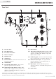
OFF ST ON GENERATOR SUB COIL AC COIL DC COIL 2 3 4 COMBINATION SWITCH 1 G G 5 B BLACK Br BROWN Y YELLOW B/W BLACK WHITE L BLUE W/G WHITE GREEN G GREEN G/Y GREEN YELLOW R RED WHITE BLUE W/L W WHITE O ORANGE C CARNATION A AMETHYST 6 Specifications G G G G R R R Y Y ENGINE DC DIODE R B R CIRCUIT BREAKER C + SPARKING PLUG CONTROL UNIT O Y L C STEPPING MOTOR (THROTTLE) DC12V Y B 5 4 6 120V TT-30R Y BATTERY B R R B G Y G/Y W G/Y W G/Y G/Y 120V 5-20RA FUSE 10A B lb
75537i ENGLISH Troubleshooting Problem Cause Solution Generator will not start No fuel Add fuel Faulty spark plug Replace spark plug Generator will not start; Generator starts but runs roughly Generator will not start wirelessly Unit loaded during start up Remove load from unit Low oil level Fill crankcase to the proper level Place generator on a flat, level surface Choke in the wrong position Adjust choke Spark plug wire loose Attach wire to spark plug Remote control battery is dead Re
ENGLISH 75537i Warranty WARRANTY CHAMPION POWER EQUIPMENT 2 YEAR LIMITED WARRANTY Warranty Qualifications Champion Power Equipment (CPE) will register this warranty upon receipt of your Warranty Registration Card and a copy of your sales receipt from one of CPE’s retail locations as proof of purchase. Please submit your warranty registration and your proof of purchase within ten (10) days of the date of purchase.
Champion Power Equipment, Inc. (CPE), The United States Environment Protection Agency (U.S. EPA.) and the California Air Resources Board (CARB) Emission Control System Warranty Your Champion Power Equipment (CPE) engine complies with both the U.S. EPA and state of California Air Resources Board (CARB) emission regulations.
EMISSION CONTROL SYSTEM WARRANTY The following are specific provisions relative to your Emission Control System (ECS) Warranty Coverage. 1. APPLICABILITY: This warranty shall apply to 1995 and later model year California small off-road engines (for other states, 1997 and later model year engines). The ECS Warranty Period shall begin on the date the new engine or equipment is delivered to its original, end-use purchaser, and shall continue for 24 consecutive months thereafter. 2.
EMISSION-RELATED PARTS INCLUDE THE FOLLOWING: (using those portions of the list applicable to the engine) Systems covered by this warranty Fuel Metering System Fuel regulator, Carburetor and internal parts Air Induction System Air cleaner, Intake manifold Ignition System Spark plug and parts, Magneto ignition system Exhaust System Exhaust manifold, catalytic converter Miscellaneous Parts Tubing, Fittings, Seals, Gaskets, and Clamps associated with these listed systems.