Installation/Operation with Service Replacement Parts Beginning with Serial No.
For future reference, record your dishwasher information in the box below.
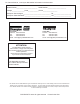
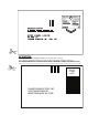
ATTENTION: Complete the back of the WARRANTY CARD above or below, then cut along the dashed lines and mail immediately to make sure that your machine warranty is validated. USE CANADIAN WARRANTY CARD IN CANADA AND USA WARRANTY CARD IN THE UNITED STATES. PLACE STAMP HERE CHAMPION INDUSTRIES INC 3765 CHAMPION BLVD.
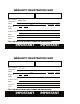
WARRANTY REGISTRATION CARD Serial # Model Date of Installation: Company Name: Address: Telephone #: ( ) --- (Street) State or Province Zip Code Contact: Installation Company: Address: Telephone #: Contact: This Card Must Be Returned to Validate Machine Warranty: IMPORTANT IMPORTANT WARRANTY REGISTRATION CARD Serial # Model Date of Installation: Company Name: Address: Telephone #: ( ) --- (Street) State or Province Zip Code Contact: Installation Company: Address: Telephone #: Contact: This
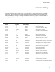
Revision History Revision History A revision might be a part number change, new instructions, or information that was not available at print time. We reserve the right to make changes to this manual without notice and without incurring any liability by making the changes. Dishwasher owners may request a revised manual, at no charge, by calling (800.858.4477) in the USA or (800.263.5798) in Canada. Revision Date Revised Pages Serial Number Effectivity Description 9.01.
Limited Warranty LIMITED WARRANTY Champion Industries Inc. (herein referred to as Champion), 3765 Champion Blvd., Winston-Salem, North Carolina 27105, and P.O. Box 301, 2674 N. Service Road, Jordan Station, Canada, L0R 1S0, warrants machines, and parts, as set out below.
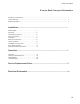
Table of Contents E-series Rack Conveyor Dishwashers Revisions to this manual......................................................................................................................... Limited Warranty .................................................................................................................................... Model Descriptions..................................................................................................................................
Model Descriptions Model Descriptions Electric high temperature single tank and multiple tank rack conveyor dishwashers with built-in electric boosters in 40°F/22°C rise or optional 70°F/39°C rise. Steam high temperature single tank and multiple tank rack conveyor dishwasher with built-in steam booster in 40°F/22°C rise or an optional 70°F/39°C rise booster. Hot water coil dishwashers utilizing recirculating hot water through a wash tank heater coil to heat the wash water.
Model Details Model Details Champion single tank and two tank rack conveyor dishwashers are fully automatic. Standard equipment includes 1HP prewash, 2HP wash and 2HP power rinse pumps. The conveyor drive is a 1/6 HP motor. All models are available in right-to-left (R-L) or left-to-right (L-R) direction. Model Numbers Single Tank - Basic.................................................. Single Tank with 22" Prewash.................................. Single Tank with 36" Prewash..............................
Installation Receiving !!ATTENTION!! Use caution when moving or lifting the dishwasher to prevent damaging the dishwasher or the installation site. Check doorway and passageway clearance before moving the dishwasher. Remove dishwasher front panels and check under the machine base for obstructions before moving. 1. Inspect the dishwasher for shipping damage 2. Check the dishwasher interior for curtains, panels and other supplies. 3.
Installation Utilities Hot Water Connections NOTE: Only qualified personnel should make dishwasher plumbing connections. Connections must meet local plumbing and sanitary codes. Improper installation is not covered be the dishwasher warranty. Hot Water Requirements: 1. Connect a 3/4" NPT hot water supply line to the line strainer located at the top rear of the dishwasher. 2.
Installation Drain Connections 1. The 1-1/2" drain line was removed and packed inside the dishwasher prior to shipping. Install the drain line once the dishwasher has been placed in its final location. 2. Dual rinse (DR) models have a PVC drain line assembly packed inside the dishwasher also. Remove this assembly and install it at the unload end of the dishwasher. The drain connection is made to the main drain line with a hose-type connector. 3.
Installation Electrical Connections WARNING: Electrocution or serious injury may result when working on an energized circuit. Disconnect power at the main breaker or service disconnect switch before working on the circuit. Lock-out and tag the breaker to indicate that work is being performed on the circuit.
Installation Electrical Connections (continued) Motor Rotation 1. Motor rotation was set at the factory. 2. The conveyor drive motor rotation is indicated by a red arrow located on the side of the motor. 3. Check if all motors are running in the wrong direction. 4. Reverse the L1 and L2 wires on the output side of the dishwasher Main Terminal Block (MTB) located inside the top-mounted control cabinet. 5. The photograph to the right shows the conveyor drive motor with its direction arrow. 6.
Installation Chemical Connections 1. Use a qualified detergent/chemical supplier for detergent/chemical and dispensing equipment needs. 2. Labeled detergent control circuit connection terminals are provided in the control cabinet for detergent and rinse agent/sanitizer dispensing equipment (supplied by others). 3. The illustration on the right, shows the terminal board for the machine. SIGNAL ONLY VENT FAN 120V COMMON 4. The signal connection points include: • Detergent signal 120VAC, 1A max load.
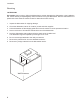
Installation Curtain Locations 1. Refer to the illustrations below and hang the curtains as shown. J-hooks are located in the corners of each section to accept the curtain rods. • • • • • Standard long curtains High hood long curtains Standard short curtains and DR High hood short curtains Final rinse curtain 24” x 20-1/4” 24” x 22-3/4” 24” x 13-/14” 24” x 20-1/4” 24” x 6-1/4” 2. Make sure the that the short flaps of the curtains face the load end of the dishwasher.
Installation Hot Water Coil Tank Heat Purging Air from the Dishwasher/Booster Heater System CAUTION: PERMANENT DAMAGE to the hot water recirculating pump can occur if the air is not purged from the dishwasher/booster heater system prior to placing the dishwasher into service. Follow the instructions carefully to prevent damage to the dishwasher hot water recirculating pump. The air trapped in the Dishwasher Hot Water Recirculating Pump and Water Lines must be purged.
Installation Hot Water Coil Tank Heat Purging Air from the Dishwasher/Booster Heater System (continued) Refer to the illustration on the previous page and follow the procedure below to purge the air from the system. Plumbing and electrical service connections must be completed before purging the system. To purge the air: 1. Make sure the dishwasher main power switch is OFF. 2. Make sure the main water supply valve located at the booster heater is OFF. 3.
Installation Door Safety Switches Dishwasher access doors are equipped with a door safety switch that automatically stops the dishwasher pumps and conveyor drive if a door is raised while the dishwasher is running. In addition, the dishwasher will not start if a door is left open. 1. If the dishwasher is running and a door is raised, then lighted GREEN START pushbutton goes out and the pumps and conveyor drive stop. 2. Check the interior of the dishwasher for any dish racks still in the machine.
Installation Removing the Spray arm End Plugs Installing the Lower Spray arm Assembly 12
Installation Installing the Lower Spray arm Assembly Removing the Spray arm End Plugs 13
Installation Removing the Dual Rinse (DR) scrap screens 1 2 14
Installation Removing the Dual Rinse (DR) scrap screens (continued) 15
Initial Start-Up Check list 1. Remove white protective film from the dishwasher exterior. 2. Install lower panels to the dishwasher. 3. Remove any foreign material from inside of the machine. 4. Check dishwasher drain/overflows are closed and in securely seated. 5. Install scrap screens and baskets and spray arms. 6. Turn main utilities the dishwasher ON. (Power, water, steam if applicable). 7. Make sure doors are closed. 8. Turn dishwasher power switch ON. 9.
Operation Operation 1. Check that the spray pipes, curtains, and scrap screens are in place and clean. 2. Check that the overflow drains are closed. 3. Check the chemical supplies. Turn on the detergent dispenser switches. 4. Turn on the exhaust vent system (if applicable), and make sure it is operating. 5. Close the door(s). Push the power switch ON, light will illuminate. Machine will begin to fill via the fill valve and the final rinse piping. 6.
Cleaning Cleaning Cleaning your dishwasher is the best maintenance you can do. The cleaning intervals below are the minimum requirements for most dishwashers. You may need to clean your dishwasher more often when washing heavily soiled wares or during long hours of continuous operation. Daily or every 2 hours of operation 1. Turn power switch to OFF. 2. Pull drain lever(s) to drain water. Remove scrap screens and scrap baskets. Clean inside of the tanks and flush with clean water.
Cleaning Cleaning (continued) At the End of the Day 1. Perform Steps 1-10 on the previous page. 2. Remove the upper and lower rinse and wash spray arms and end plugs and flush with fresh water. 3. Remove the Dual Rinse (DR) rinse arm assemblies and flush with fresh water. 4. Clean the final rinse arm nozzles using a small paper clip. 5. Remove the curtains and clean with fresh water. DO NOT USE STEEL WOOL TO CLEAN THE INTERIOR OF THE MACHINE.
Maintenance Maintenance Weekly 1. Inspect all water lines for leaks and tighten at joints if required. 2. Clean any detergent residue from the exterior of the machine. 3. Check that the drain/overflow pipes seat tightly in their drains. 4. Clean any accumulated scale from the heating element. 5. Inspect the spray arms for any damage or missing parts. 6. Inspect the final rinse arms for missing parts. 7. Inspect the pawl bar and drive assembly for damage or missing parts. 8.
Blank Page This Page Intentionally Left Blank 21
Digital Display E-Rack Digital Temperature Display Meters ATTENTION: The Digital Temperature Displays only indicate temperature, they do not control wash tank or final rinse booster heaters. Electro-mechanical thermostats continue to control the tank and final rinse heat circuits. 1. The analog temperature gauges have been replaced with digital temperature display meters. 2.
Digital Display The set-point determines how the meter displays the yellow & green bar. For example, if the set-point is 70, then the bar displays yellow from 0-70 then green from 70 and above.
Digital Display Calibration: Calibration is an internal function of the display circuit board and does not calibrate temperature control of the dishwasher components. NOTE: The Thermister Plug and 1 wire from the Rinse Switch Connector must be disconnected from the display circuit board before calibration. To calibrate the display board: 1. Turn dishwasher Power Switch OFF. 2. Disconnect the thermister plug and at least 1 wire from the rinse switch connector. 3. Turn Power Switch ON. 4.
Digital Display Display Codes and Definitions The illustrations below show the codes that may appear in the temperature meter displays.
Troubleshooting Before calling for service check the following conditions. 1. Dishwasher main power and water supply is on. 2. Machine has been assembled correctly. 3. Conveyor is clear of any obstructions. 4. Drains are closed. 5. Screens and pump intake screens are clear. 6. Doors are closed and secure. Condition Solution Dishwasher will not run. Door not closed. Main power OFF. Dishwasher OFF. Dish rack inserted wrong Close door completely. Check breaker on panel. Turn dishwasher ON.
Service Replacement Parts Illustration..................................................................................................................................... Page Prewash Doors and Panels........................................................................................................................... 28 Single Tank Doors and Panels...................................................................................................................... 30 Two Tank Doors and Panels........
Prewash Doors & Panels 22 25 24 23 6 9 10 7 8 8 12 26 16 18 11 12 5 12 15 4 3 13 14 12 21 12 2 19 20 1 (L-R Direction Shown) 28 17 11
Prewash Panels & Doors Item No. Part No. Description Qty. 1 328977 Panel Assy. Front Perimeter 22" PW Prewash 1 - 328978 Panel Assy.
Single Tank Doors & Panels 19 20 21 9 22 11 27 25 29 5 3 6 23 9 24 26 8 28 7 10 11 4 2 18 16 11 15 14 2 (L-R Direction Shown) 30 17 12 1 13
Single Tank Doors & Panels Item No. Part No. Description Qty. 1 328974 Panel Assy., 44 Front Perimeter 1 - 330981 Panel Assy.
Two Tank Doors & Panels 26 25 27 26 28 29 25 27 28 29 16 1 2 3 15 17 18 13 10 4 4 5 3 9 4 9 14 10 11 6 10 12 5 7 3 24 23 22 21 8 20 19 32
Two Tank Doors & Panels Item No. Part No. Description Qty.
Drive Motor Assembly 3 1 15 16 7 2 4 13 5 13 17 11 7 11 18 9 12 6 8 10 14 34
Drive Motor Assembly Item No. Part No. Description Qty. 1 0509199 Drive Motor Switch 1 2 327918 Bracket, Motor Switch Mounting 1 3 See Sheave and V-Belt Chart Below 4 327916 Plate, Drive Motor Mounting 1 5 327920 Plate, 44 Motor Assy Mounting 1 5 327917 Plate, 64 Motor Assy Mounting 1 6 327919 Bracket, Motor Spring Mounting 1 7 106482 Washer Lock 1/4 Split SST 4 8 102376 Washer, Flat 5/16 x 3/4 x .06 SST 2 9 113702 Spring 0.6OD x 0.095 Wire x 1.
Conveyor Drive Assembly 10 11 1 2 3 12 4 13 5 19 6 7 8 9 18 Tank Bottom 21 14 20 22 15 23 19 16 24 20 21 17 24 25 36
Conveyor Drive Assembly Item No. Part No. Description Qty. 1 202381 Roller Crosshead 1 2 100868 Roller Stud Crosshead 1 3 107089 Nut Jam 1/2-13 1 4 206300 Crank, Rack Arm 1 5 206301 Shaft 5/8" O.D. x 8-3/8" LG.
Prewash Track & Cradle Assembly 12 19 13 14 11 14 10 8 7 19 6 4 9 20 2 17 15 3 18 23 22 Tank 17 5 1 16 17 18 20 19 21 38 23 18
Prewash Track & Cradle Assembly Item No. Part No. Description Qty.
SingleTank Track & Cradle Assembly 16 13 12 11 17 14 23 15 25 15 24 17 18 9 23 10 2 1 22 21 19 8 7 (For DR, DRWS Models Only) 6 4 5 1 20 (For WS and LT Models Only) 40
Single Tank Track & Cradle Assembly Item No. Part No. Description Qty.
Two Tank Track & Cradle Assembly 13 15 12 18 17 21 11 14 18 21 23 10 16 22 17 21 10 16 18 9 21 18 19 20 5 4 6 7 2 3 1 42 8 20
Two Tank Track & Cradle Assembly Item No. Part No. Description Qty.
Prewash Screens 2 1 44
Prewash Screens Item No. 1 2 Part No. Description Qty.
Single Tank Scrap Screens Tank 3 2 1 Tank 5 4 4 46
Single Tank Scrap Screens Item No. 1 2 3 4 5 Part No. Description 414328 414329 414300 331922 328653 Screen, E-44 L-R Front Screen, E-44 L-R Rear Basket, Rack Support, Screen Screen, Outboard, (E54DR) Qty.
Two Tank Scrap Screens 3 3 2 4 2 5 1 5 1 4 5 5 48
Two Tank Scrap Screens Item No. 1 2 3 4 5 Part No. Description 414328 414329 414300 331922 328653 Screen, E-44 L-R Front Screen, E-44 L-R Rear Basket, Rack Support, Screen Screen, Outboard, (E-84 Only) Qty.
Prewash Spray Arms 17 6 16 15 18 14 8 4 13 5 2 12 11 10 9 Rear Wall of Hood 3 12 7 3 5 12 9 4 2 1 19 50
Prewash Spray Arms Item No. 1 2 3 4 5 6 7 8 9 10 11 12 13 14 15 16 17 18 19 Part No. 414569 113723 113738 113540 113542 328028 414568 328998 113555 113716 328634 106014 106482 106026 329000-1 106141 100735 329001 328253 Description Wash Manifold Assembly 6” Lower O-Ring,1.
Single Tank Wash Spray Arms 15 6 14 11 13 5 12 2 4 10 Rear Wall of Hood 18 17 16 7 17 3 17 5 8 2 1 3 4 9 52 9 8
Single Tank Wash Spray Arms Item No. Part No.
Two Tank Wash & Rinse Spray Arms 14 12 19 11 18 17 8 15 1 14 16 12 2 11 13 4 7 Rear Wall of Hood 2 1 11 3 1 4 Rear Wall of Hood 11 3 3 4 9 2 11 10 3 11 1 2 9 4 10 5 9 10 9 10 54 5 6 6
Two Tank Wash & Rinse Spray Arms Item No. Part No. 1 2 3 4 5 --6 --7 --8 --9 10 11 12 13 14 15 16 17 --18 19 113542 113540 113738 113723 414289 414288 414291 414290 414318 328443 414319 328445 113555 113716 106014 106482 328034 106026 100141 328998 329000-1 329000-2 329001 100735 Description Qty. Gasket, Flat EDPM 2-3/8 ID 4 Locknut 2NPT SST 4 Block, Washarm Retaining 2 O-ring,1.
Float Switches Two Tank Single Tank Prewash 4 3 2 1 56
Float Switches Item No. Part No. Description Qty.
Single Tank Electric Heat 1 2 3 4 3 5 6 58
Single Tank Electric Heat Item No. Part No. 1 2 3 4 5 6 113516 113517 113518 113519 100153 104618 108345 106407 100140 Description Heater 15/18KW 208V,380V Heater 15/16.3KW 230/240V, 400/415V Heater 15/16.3KW 460/480V Heater 15KW 575V Bolt, 3/18-16 x 1 Hex Head Washer 3/8 x 7/8 x 1/16 SST Gasket 3 x 3 x 1/8” 2” Hole Washer Lock 3/8 Split Nut Plain 3/8-16 Qty.
Two Tank Electric Heat 3 1 A Tank 2 2 60 Wash Rinse
Two Tank Electric Heat Item No. Part No. Description Qty. 1 2 3 113516 113517 113518 113519 108345 113804 118842 113883 113884 Heater 15/18KW 200/220V (Wash) Heater 15/16.3KW 230/240V(Wash) Heater 15/16.3KW 460/480V (Wash) Heater 15KW 575V (Wash) Gasket 3 x 3 x 1/8” 2” Hole Heater 10/12.
Two Tank Steam Heat with K2 Steam Booster 11 10 8 2 2 9 1 6 5 7 3 2 4 1 62 8 5
Two Tank Steam Heat with K2 Steam Booster Item No. Part No. 1 2 ----3 4 5 6 7 8 9 10 11 109069 109887 109903 108516 105782 104649 111380 100123 100263 108345 110189 327907 327908 Description Thermostat, Control Valve, 3/4" Solenoid 120VAC Kit, Repair Solenoid Valve Coil, Replacement 120VAC Union 1/2 NPT BI Relief, Valve Trap, Steam I/2" Cock, Gauge 1/4" Strainer, Line 1-1/4" BI Gasket Booster, K2 Spirec Coil, Steam R-L Coil, Steam L-R Qty.
Single Tank Steam Heat 1 3 2 4 5 6 8 7 Tank 64
Single Tank Steam Heat Item No. 1 1 2 3 4 5 6 7 8 9 Part No. 327908 327907 102554 100548 113918 100740 102376 108345 106013 100154 Description Qty.
Two Tank Steam Heat 7 9 8 1 10 2 3 Tank 3 5 6 4 Tank 66
Two Tank Steam Heat Item No. 1 2 3 4 5 6 7 8 9 10 Part No. 327907 100740 102376 108345 106013 100154 327908 102554 100548 113918 Description Coil, Steam LH Bolt 5/16-18 x 1 Hex Head Washer 5/16 X 3/4 x 1/16 Gasket 3 x 3 1/8” 2IN Hole Washer Lock 5/16 Split Nut Plain 5/16-18 Coil, Steam RH Union 3/4 SST Locknut, 3/4NPT SST Nipple, Rtoe 3/4 x 1-3/4 Qty.
Thermostats Two Tank Single Tank 2 4 5 Front of Tank Wall 3 1* 2 1 68 1
Thermostats Item No. Part No. 1 -1* 2 -3 -4 -5 109069 109069 109069 110561 110561 201041 201041 109034 109034 100547 100547 Description Thermostat w/capillary - Single Tank Thermostat w/capillary -Two Tank Thermostat w/capillary -DR Models Only Thermostat, Fixed Hi Limit - Single Tank Thermostat, Fixed Hi Limit -Two Tank Washer 7/8 ID x 1/8 Thk - Single Tank Washer 7/8 ID x 1/8 Thk - Two Tank Gasket. Plug - Single Tank Gasket.
E-Series Thermostat and Junction Box Thermistor Connection Block 1 1 2 Inter-wiring Connection Block 1 8 3 5 3 4 2 6 5 12 10 9 11 Thermistor Assembly for Wash Tanks NOTE: Components and Quantities vary per Machine.
E-series Thermostat and Junction Box Item No. Part No. 1 2 3 4 4 5 6 7 8 9 10 11 12 114521 114520 114519 114518 114516 114515 114517 114512 114522 114435 0512299 0501836 201029 Description End Cover, Single Terminal, D-MZB Terminal, Single MZB, 1.5 NS35 End Block, E/NS 35 N End Cover, Double Terminal STTB 2.5, End Cover, Single Terminal D-ST 2.5 Terminal, Single, Ground ST 2.5 (Green) Terminal , Double STTB 2.5 Terminal, Single ST 2.
Prewash Drain-overflow Assembly 1 4 3 2 1 5 6 7 Tank Bottom 4 8 9 72
Prewash Drain-overflow Assembly Item No. Part No. 1 2 3 4 5 6 7 8 9 108875 328824 206419 106026 328430 111532 100735 112257 111034 Description Ring, Retaining Lever Drain Lift Rod, Overflow Lift 22"PW Washer 1/4 x 5/8 x 1/6 SST Overflow PW Mtd O-ring, Overflow Bolt 1/4-20 x 5/8 Hex Head O-ring, drain Drain , Flange Cast/Mach SST Qty.
Single & Two Tank Drain-overflow Assembly 1 3 4 2 12 Rinse 414897 Includes: 1 Jam Nut- 108521 O-ring - 111532 11 5 13 Rinse Overflow328993 14 Overflow Cover328984 Wash 414971 Includes: 9 1 Jam Nut- 108521 7 O-ring - 111532 Wash Overflow328982 8 Tank Bottom Oveflow Cover328984 6 10 74
Single & Two Tank Drain-overflow Assembly Item No. Part No. 1 2 3 4 5 6 7 8 9 10 11 ---12 13 14 113715 328985 206442 206444 107966 112257 100735 106026 111532 111034 ------------------107367 107966 107368 Description Ring, Retaining Lever Drain Lift Rod, Overflow Lift Block, drain lift Nut, Grip 10-32 w/Nylon Insert O-ring Bolt 1/4-20 x 5/8 Hex Head Washer 1/4 x 5/8 x 1/6 SST O-ring, Drain 1.600 ID x .
Final Rinse Piping with Booster 21 16 15 14 17 20 13 From Booster 12 11 18 22 8 19 10 7 9 Top of Hood 4 1 6 2 3 5 76 Manifold Dimension in Chart is center to center of upper and lower spray pipe.
Final Rinse Piping with Booster Item No. Part No. 1 2 3 See Chart Below for Manifold P/N's 106026 Washer 1/4 x 5/8 x 1/16 SST 1 107967 Nut Grip 1/4-20 w/Nylon Insert 1 4 5 See Chart Below for Upper Nozzle P/N's 3 See Chart Below for Lower Nozzle P/N's 3 6 -7 8 9 10 11 12 13 14 15 16 17 18 19 20 21 22 113795 113716 100156 100599 105976 101259 100184 100571 102470 102388 104429 900837 102525 109879 100171 102490 100135 102442 Model Description Qty.
Fill Piping No Booster or Steam Booster 15 14 20 21 5 5 9 18 6 11 5 12 8 23 10 7 19 22 6 11 5 4 3 1 78 2 19 16 17
Fill Piping No Booster or Steam Booster Item No. 1 2 3 4 5 6 7 8 9 -10 11 12 --13 14 15 16 17 18 19 20 21 22 23 Part No.
80 9 30 11 15 6 26 14 24 4 5 3 28 17 3 29 12 31 29 20 Left to Right Shown 3 7 27 3 17 25 3 12 16 16 19 22 25 3 3 1 2 8 7 18 21 13 23 10 Fill Piping with Booster
Fill Piping with Booster Item No. Part No. 1 2 3 4 5 6 --7 8 9 10 11 12 13 14 15 16 17 18 19 20 21 22 --23 24 25 26 27 ----28 ----29 30 31 100135 100171 100184 100206 100209 100500 900836 100571 100599 100709 101259 101397 102104 102388 102435 102438 102442 102444 102470 102490 102521 102525 104429 900836 105976 107550 109879 110768 111437 109903 111472 113352 113392 113357 114384 201029 311694 Description Gauge, Pressure 0-60 PSI Bushing, Red.
Cold Water Thermostat (CWT) Piping 7 8 1 14 9 5 12 4 3 6 6 11 15 17 18 10 PREWASH TANK 16 19 22 21 20 6 11 13 6 82 2
Cold Water Thermostat (CWT) Piping Item No. Part No. 1 2 3 4 5 6 7 8 9 --10 11 12 13 14 ----15 16 17 18 19 20 21 22 100209 100573 100947 101262 102388 102422 102438 104421 107069 900836 107315 109909 110134 112109 113352 113392 113357 319549 328539 100547 107922 107966 109069 201041 106460 Description Nipple, 1/2" NPT Close, Brass Locknut, 1/2" NPT Brass Nipple, 1/4" NPT Close Brass Nipple, 1/4" NPT x 1-1/2" Lg.
Final Rinse Drain Assembly 1 2 4 3 5* *Not a Part of Item 3 must order separately 84
Final Rinse Drain Assembly Item No. Part No. 1 2 3 4 5 100141 305218 107342 112045 107473 Description Nut, Grip 1/4-20 Strainer, F/R Drain Drain basket assy. (Does not include Item 5) Washer,tailpiece (Comes with Item 3) Tailpiece Qty.
Prewash Pump Suction & Discharge 1 2 7 3 A 9 Discharge 5 5 4 6 L-R Application Shown 86 Suction
Prewash Pump Suction & Discharge Item No. 1 2 3 4 5 6 7 8 9 10 Part No. Description Qty.
Wash & Rinse Pump Suction/Discharge 7 1 2 3 6 5 A 4 B 88
Wash & Rinse Pump Suction/Discharge Item No. 1 2 3 4 5 6 7 Part No. Description Qty.
1 2 21 4 90 3 5 6 9 10 7 11 8 2 14 12 15 13 19 16 17 18 20 Pump/Motor Assembly
Pump/Motor Assembly Item No. Part No. Description Qty.
Electric Booster Assembly - 40°F/60°F Rise Prior to S/N RE3932 The booster tank heater with the center hole for inserting the high-limit thermostat is no longer available. Use the fitting on the corner of the booster tank to install the high-limit thermostat.
Electric Booster Assembly - 40°F/60°F Rise Item No. Part No. 1 2 3 --4 5 6 7 8 113690 113885 113886 113887 111233 111232 111234 111383 109985 113724 110561 108576 109069 102505 414331 113690 113885 113886 112059 111334 112060 112061 328254 113706 108954 328048 111235 111236 111237 111384 9 10 11 12 13 Description Qty.
Electric Booster Assembly - 70°F Rise Prior to S/N RE3932 The booster tank heater with the center hole for inserting the high-limit thermostat is no longer available. Use the fitting on the corner of the booster tank to install the high-limit thermostat.
Electric Booster Assembly - 70°F Rise Item No. Part No. 1 2 3 --4 5 6 7 8 9 10 11 12 13 113690 113885 113886 113887 109985 113724 110561 108576 109069 102505 414331 112059 111334 112060 112061 328254 113706 108954 328048 109458 Description Qty.
Control Cabinet 13 19 20 15 18 12 22 22 21 11 32 31 16 27 23 24 29 17 28 25 26 30 10 10 4 9 8 7 6 2 1 96 3 5 8
Control Cabinet Item No. Part No. Description Qty.
Control Cabinet Item No. Part No. Qty. 18 111625 Starter, Mtr., 1/6HP Drive 200-220/208-240V/60/1, 1.0-1.6A 1 --- 111624 Starter, Mtr., 1/6HP Drive 208-220, 230-240V/60/3, .63-1.0A 1 --- 111623 Starter, Mtr., 1/6HP Drive 460-480V/60/3, .4-.63A 1 --- 111622 Starter, Mtr., 1/6HP Drive 575V/60/3, .24-.4A 1 19 113161 Starter, Mtr., 1HP Prewash 200-220/208-240V/60/1, 9.0-14.0A 1 --- 111628 Starter, Mtr., 1HP Prewash 200-220/208-240/60/3, 4.0-6.
Control Cabinet with Digital Display Parts Illustration is on Page 100 Item No. Part No. Description Qty. 1 2 3 4 ----------5 6 7 8 9 10 11 12 --13 14 --15 16 17 18 19 20 21 111980 702084 0512213 114436 114438 114439 114532 114437 114532 114508 114489 107171 100294 113910 113936 111277 109064 107091 112424 111821 112901 111036 111067 114520 114521 111827 103310 111833 Power Switch, Ciircuit Breaker LED Assy.
1 27 2 12 28 3 10 7 13 14 3 26 25 COMMON 30 29 8 25 25 RINSE AID 120V 100 SIGNAL ONLY 9 15 16 22 4 23 11 24 21 5 6 17 18 20 19 19 * * ** * ** 5 6 * See Item 11 on pg. 97 for P/N’s ** ** See Item 12 on pg.
Control Cabinet with Digital Display Continued from Page 99 Item No. Part No. Description Qty. 24 111630 Starter, Mtr., 2HP Wash 200-220/208-240V/60/1, 13.0-18.0A 1 --- 111629 Starter, Mtr., 2HP Wash 200-220/208-240V/60/3 6.0-10.0A 1 --- 111627 Starter, Mtr., 2HP Wash 460-480V/60/3 2.5-4.0A 1 --- 111627 Starter, Mtr., 2HP Wash 575V/60/3 2.5-4.0A 1 --- 113161 Starter, Mtr., 3HP Was/Rinse 200-220/208-240V/60/3 9.0-14.0A 1 --- 111628 Starter, Mtr., 3HP Wash/Rinse 460-480V/60/3 4.
Extended Vent Cowls 2 1 4 5 5 2 2 4 6 A 102 2 3
Extended Vent Cowls Item No. Part No. 1 2 3 4 5 6 Description Qty.
Standard Vent Cowls 5 2 1 5 2 4 2 4 2 3 6 8 7 104
Standard Vent Cowls Item No. 1 2 3 4 5 6 7 8 -- Part No. Description 401487 201589 112258 108954 104883 307228 100734 100141 Vent Stack Assembly (Includes items 2-5) Regulator Assembly Nut, Wing 1/4-20 SST Nut, Grip 6-32 w/Nylon Insert Screw 6-32 x 3/8 Round Head Vent Hood Belt 1/4-20 x 1/2” Hex Head Nut Grip 1/4-20 401889-S Vent Hood Assembly (Includes Items 1-10) Qty.
E-44DR Dual Rinse Assembly 1 2 5 6 3 4 4 16 17 16 17 9 See page 104 for pump breakdown 18 19 8 7 10 13 5 15 20 11 14 39 21 12 22 26 23 24 25 37 29 27 28 30 31 32 34 35 106 33 36 38
E-44DR Dual Rinse Assembly °°Item No. Part No. Description Qty. 1 2 3 4 5 6 7 8 9 10 11 ------- 329167 114291 114290 107290 329009 329562 329281 331017 329465 111443 113986 113987 113988 113989 Manifold, E44DR Aux. Rinse O-ring Washer, rubber Nozzle tube, weld horizontal Screen RH Screen LH basket, screen Screen Switch, float Element 3.2/3.9KW 200-220V/60/1-3 Element 3.2/3.9KW 220-240V/60/1-3 Element 3.2/3.9KW 400-460V/60/3 Element 3.2/3.
E-44DR Recycle Pump Assembly 1 2 3 4 6 7 108 5
E-44DR Recycle Pump Assembly Item No. Part No. Description Qty.
Single Tank Hot Water Coil Heat 3 2 7 9 5 1 8 10 14 13 7 6 12 5 11 4 16 11 17 15 110
Single Tank Hot Water Coil Heat Item No. Part No. 1 100118 2 100123 3 100184 4 102396 5 102396 6 102444 7 102490 8 102775 9 103486 10 107418 11 109879 12 111854 13 111860 14 114463 15 319273 16 332841 Description Union Elbow, 3/4" NPT Male Brass Petcock 1/4" Female Brass Nipple, 3/4" NPT x Close Brass Bushing Reducing, 1" NPT x 3/4" NPT Brass Elbow 3/4" NPT x 90° Brass E;bp 34"NPT x 90° Brass Nipple 3/4" NPT x 3-1/2"Lg. Brass Nipple, 1" NPT, 8"Lg. Brass Nipple 3/4" NPT x 22" Lg.
Double Tank Hot Water Coil Heat 24 39 8 18 37 22 41 17 33 13 40 9 20 5 10 34 4 36 19 23 32 31 25 3 2 44 14 7 1 43 12 30 21 11 112 29 42 16 27 26 15 38 6 35 28
Double Tank Hot Water Coil Heat Item No. Part No.
24" Sideloader 11 10 9 1 8 2 3 4 5 6 7 114
24" Sideloader Item No. Part No. 1 2 3 4 5 6 7 8 --9 --10 11 329927 329352 312336 312335 109282 108875 328955 328941 328942 329317-1 329317-2 313598 328914 Description Baffle, Sideloader Panel, End Bracket, Bar Support Pawl, Pin, Bar Support Spacer Pin, Cotter 3/32" x 1/2" Bracket Support, Sideloader 24" L-R Sideloader 24" R-L Sideloader 24" Track, R-L Sideloader 24" Track, L-R Sideloader Lever, Pawl Bar, Pawl 13-1/2" Lg. Qty.
30" Sideloader 11 10 9 1 8 3 4 5 6 7 116 2
30" Sideloader Item No. Part No. 1 2 3 4 5 6 7 8 --9 --10 11 329927 329352 312336 312335 109282 108875 328955 328943 328944 329318-1 329318-2 313598 328915 Description Baffle, Sideloader Panel, End Bracket, Bar Support Pawl, Pin, Bar Support Spacer Pin, Cotter 3/32" x 1/2" Bracket Support, Sideloader 30" L-R Sideloader 30" R-L Sideloader 30" Track, R-L Sideloader 30" Track, L-R Sideloader Lever, Pawl Bar, Pawl 19-1/2" Lg. Qty.
Dish racks 2 1 118
Dish racks Item No. Part No. 1 2 101285 101273 Description Qty.
Blank Page This Page Intentionally Left Blank 120