
User's Guide

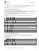
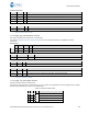
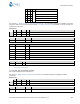

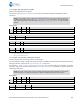
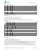
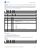
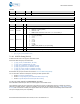

Table Of Contents
- 1. Introduction
- 2. Getting Started
- 3. Operational Examples
- 3.1 System Setup Examples
- 3.2 Cable Replacement Examples with CYSPP
- 3.3 Remote Control Examples with CYCommand
- 3.4 GAP Peripheral Examples
- 3.5 GAP Central Examples
- 3.6 GATT Server Examples
- 3.7 GATT Client Examples
- 3.8 Security and Encryption Examples
- 3.9 Beacon Examples
- 3.10 Performance Testing Examples
- 3.11 Device Firmware Update Examples
- 4. Application Design Examples
- 5. Host API Library
- 6. Troubleshooting
- 7. API Protocol Reference
- 8. GPIO Reference
- 9. Cypress GATT Profile Reference
- 10. Configuration Example Reference
- Revision History

API Protocol Reference
EZ-Serial BLE Firmware Platform User Guide, Doc. No. 002-11259 Rev. *E 170
See Section 8.1 (GPIO Pin Map for Supported Modules) for a pin map table showing pin availability and default
assignment.
NOTE: Enabling PWM output on one or more channels will automatically prevent the CPU from entering deep sleep
under any circumstances. This happens because the high-frequency clock required to generate the PWM signal cannot
operate while the CPU is in deep sleep. To allow deep sleep mode again, you must disable all PWM output. Refer to
Section 3.1.5 (How to Manage Sleep States) for further detail.
Binary Header:
Type
Length
Group
ID
Notes
CMD
C0
08
09
0B
None.
RSP
C0
02
09
0B
None.
Text Info:
Text Name
Response Length
Category
Notes
SPWM
0x000A
SET
None.
Command Arguments:
Data Type
Name
Text
Description
uint8
channel
N*
Channel number (0-3)
uint8
enable
E
Enable PWM output (0 to disable, 1 to enable)
uint8 divider D
Clock divider value (24 MHz input):
• Minimum = 0 (factory default)
• Maximum = 255
• NOTE: Divider denominator is divider+1, so “0” is “divide by 1”
uint8 prescaler S
PWM prescaler value:
• 0 = 1x (no prescaling)
• 1 = 2x
• 2 = 4x
• 3 = 8x
• 4 = 16x
• 5 = 32x
• 6 = 64x
• 7 = 128x
• NOTE: Factory default is 0 (1x, no prescaling)
uint16
period
P
Period (0-65535)
uint16
compare
C
Compare (0-65535, must not be greater than period)
Response Parameters:
None.
Related Commands:
• gpio_get_pwm_mode (GPWM, ID=9/12)
7.2.9.12 gpio_get_pwm_mode (GPWM, ID=9/12)
Obtain current PWM output behavior for selected channel.
See Section 8.1 (GPIO Pin Map for Supported Modules) for a pin map table showing pin availability and default
assignment.
Binary Header:
Type
Length
Group
ID
Notes
CMD
C0
01
09
0C
None.
RSP
C0
09
09
0C
None.