
Use and Care Manual


3
110496-1
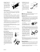
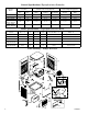
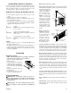
• Install window panel
retainers. Place two
panel retainer strips onto
bottom of neck flange
and position to the width
of the window. Cut the
strips to fi t if necessary.
These strips hold the
window fill-in panels
(Fig. 3).
• Position cooler in win-
dow. Position neck of
cooler so that bottom of neck fl ange rests on window sill and fl ange
(E-Fig. 2) is snug against edge of sill (H-Fig. 2). With cooler in
position, hook the “S” hooks into the holes of the top pan near the
back of the cooler (B-Fig. 2).
• Break fi ll-in panels to fi t. With cooler installed, as described
above, measure for each window fi ll-in panel and score with sharp
knife and straight edge guide to desired width. To break window
fi ll-in panels, the panel should be laid over the edge of a straight fl at
surface at the point to be broken off. Apply pressure on the edge
of the panel that extends over the edge of the surface and break off
unwanted piece.
• Install fi ll-in panels. Place one window fi ll-in panel on each side
of grill and into panel retainer strip at bottom of grill. Place the
other panel retainer strips onto top of neck fl ange and fi ll-in panels.
Be sure the panels are snug up against cooler neck.
• Place window behind retainer strip. Raise back of cooler so that
the window (D-Fig. 2) may be brought down behind top of panel
retainer strip (C-Fig. 2).
• Level Cooler. Adjust the chains to level the cooler.
• Adjust house legs. Pull out house legs so that the rubber bumpers
rest against house siding (F-Fig. 2). Tighten screw in retaining
collar. (G-Fig. 2).
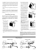
Connecting Water
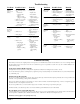
• Install overfl ow assembly. Remove
nut and place nipple through the hole in
the pan, with the rubber washer between
the pan and the head of the drain nipple
(Fig. 4). Screw on nut and draw up tight
against bottom of pan. Insert overfl ow
pipe in nipple to retain water. Overfl ow
pipe may be removed to drain pan when
necessary. A garden hose may be
screwed on the drain nipple to
drain water away from your unit.
• Connect water supply line. In-
stall a sillcock and water valve on
faucet as shown by fi gure 5. Place
the nut and ferrule on the tubing
and tighten the nut until water
tight.
Maintenance
WARNING: Before doing any maintenance be sure power is
off and unit is unplugged. This is for your safety.
Spring Start-Up
• Oil bearings. The blower bearings and cooler motor in this unit
should be oiled with a few drops of non-detergent 20/30 weight oil
once each year. The motor does not need oil if it has no oil lines
for oiling. Motors that have no oil lines are lifetime oiled at the
factory and require no further oiling for the life of the unit.
CAUTION: Do not over oil.
Over oiling can cause motor burn
out, due to excessive oil getting into
motor winding.
• Check belt tension. A 3 lb. force
should defl ect the belt 3/4 inches (see
Fig. 7). Readjust belt if needed.
• Clean pump. Cleaning the pump is necessary once a year at start-
up. For your safety, turn unit off and unplug from power receptacle.
Remove the pump from the mount slot. Remove the base of the
pump as shown in Fig. 8. Clean the pump and turn the impeller
to ensure free operation. Remove the pump spout and check for
any blockage. After cleaning,
reinstall the base onto the pump.
Press fi rmly to make sure it is
secure. Reattach the pump to
the mount in the cooler using
the plastic retainer to ensure that
the pump will not overturn. Do
not forget to replace the spout
and water delivery tube onto the
pump outlet.
• Replace Pads. Aspen pads should be replaced once or twice a
season, depending upon the length of the season. At the beginning
and at mid season a clean pad is more absorbent and effi cient and
will deliver substantially more cool air.
Winter Shut Down
• Drain water. Always drain all of the water out of the cooler and
water supply line when not in use for prolonged periods, and par-
ticularly at the end of the season. Keep the water line disconnected
from both the unit and water supply so that it does not freeze.
• Cover unit. To protect the life of the fi nish, a cover for the unit is
suggested in extended periods of non use.
• Install fl oat valve. Install
valve in the provided hole in
corner post (Fig. 6) and attach
water supply line.
• Fill pan. Allow water to fi ll
to within 1” of the top of the
overfl ow pipe and adjust fl oat
to maintain this water level.
This can be accomplished by
bending the float rod (Fig.
6).
Impeller
Remove
Base
Fig. 8
Fig. 3
Window Fill-In
Panels
Top Panel
Retainer
Bottom Panel
Retainer
Rubber Washer
Overfl ow Pipe
Nipple
Bottom Pan
Nut
Fig. 4
Faucet
Water Supply
Valve
Sillcock
Ferrule
Nut
Fig. 5
Float Rod
Water Supply
Line
Washer
Nut
Ferrule
Nut
Fig. 6
Corner Post
Fig. 7
3 Lb.
3/4 Inches