
Use and Care Manual


4
110496-1
• Cover grill. To help keep out cold air you can use the optional
plastic grill cover. This cover may be purchased from your local
distributor. To install the cover, line up the grill cover with the grill
so that the tabs on the cover will slide over the center section of the
grill. Slide the grill cover onto the grill. The tabs will snap into
place. To remove, just pull the grill cover straight forward away
from the grill.
• Unplug unit from power supply during extended periods of
non-use.
By following the operating, installation, and maintenance suggestions
as outlined, you can get many years of effi cient and satisfactory
service from your cooler. In the event additional information is
desired, your dealer will be more than glad to assist you in every
possible way.
Vertical Duct Conversion
This window unit can be reconfi gured to a vertical tunnel con-
fi guration for installation into smaller width openings. Follow the
subsequent steps if this is desired. Note: Tunnel mount strips used
to convert tunnel are not shipped with this cooler. If desired,
call Customer Service at 1-800-643-8341 to have it shipped to
you at no cost.
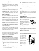
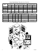
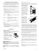
1. Remove the 9 screws
from the sides and bot-
tom of the tunnel.
2. Remove the top 4 mid-
dle screws of the top
pan while holding the
tunnel in place (Fig 9).
Be careful not to drop
the tunnel, or damage
to the electric cords
could occur. You may
need to loosen other
screws in the top pan
to make it easier to remove the tunnel.
3. Rotate the tunnel 90 degrees counter-clockwise (Fig 10). Be care-
ful as you rotate the tunnel that you don’t damage or disconnect
the cords which are still connected to the controls and the front
panel.
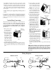
4. Insert the fl ange of the tunnel
between the front panel and the
top pan. Line up the two larger
holes in the tunnel with the
center two holes of the top pan.
(Fig 11).
5. Using the screws taken from the
top pan, secure the tunnel to the
unit. Do not tighten the screws,
leave them loose until the rest of
the tunnel has been secured.
6. Line up the three holes at the
bottom of the tunnel with
the holes in the front panel.
Using the screws taken from
the bottom of the tunnel pre-
viously, secure the tunnel to
the front panel.
7. Make sure all the screws re-
moved from the top pan are in
place and tighten all screws.
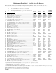
8. Skip this step for the RWC35
& RN35W models. Remove
the three screws (2 in models
WC37 & N37W) from each
side of the front panel as
shown in fi gure 12.
CAUTION: Make sure that
you do not remove the bottom
most screw. It holds the blower
housing in place.
9. To cover up the gap in the front
panel, use the two strips of metal
obtained from Customer Service.
Line up the holes in the metal strips
to the holes in the front panel and
secure them with the screws pre-
viously removed in step 8. (See
Fig. 12) Install the metal strips so
that there is no gap between the
top pan and the metal strip. If there is a gap, turn the metal strip
around.
NOTE: When mounting a cooler with this type of vertical tunnel
confi guration, the unit should be supported by a fl at support or
stand. The installation method mentioned in the owner’s manual
using chains and legs should not be used. The fi ller panels in
the installation kit may be used to seal off the window above the
cooler duct.
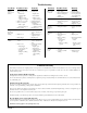
Wiring Diagrams
Manual Control Remote Control
Hi
Low
Gnd
Com.
Black
Red
Green
White
Plug Switch
Blower Motor
Pump
Motor
Hi
Low
Gnd
Com.
Black
Red
Green
White
Ground
Wire
Blower Motor
Pump
Motor
LockPlate
w/ Grommet
Control
Ground
Screw
Fig. 9
Remove top
screws last. Do
Not Drop Tunnel
Fig. 10
Fig. 11
Line up to the two
middle holes
Fig. 12
Do Not Remove
Bottom Screw
Metal
Strip