Off-Air Antenna Installation Guide Solutions For The Professional Installer
INTRODUCTION T he information in this manual has been gathered from some of the most experienced antenna installation professionals in the country and compiled by Channel Master ® field engineers. It is intended for technicians who are, or plan to become professional antenna installers. Any handy “do-it-yourself” consumer can mount an antenna, run transmission line and pull in some kind of a signal.
CHAPTER ONE: ANTENNA SELECTION B asically, a receiving antenna is a device for intercepting the electromagnetic waves or signals, sent from a transmitter. Some antennas are simple vertical poles; others are small wire loops attached to the back of a TV set. In this manual, we will discuss the outdoor TV antenna design with which most of us are familiar: a central horizontal boom with small elements attached at right angles. The main receiving element of an antenna is called the dipole (Fig. 1-1).
Fig. 1-2. A VHF/FM broadband TV antenna. Fig. 1-1. The principal parts of a basic Yagi-type TV antenna. Fig. 1-6. FM antenna. Fig. 1-3. Various designs of UHF TV antennas. Fig. 1-5. Channel Master ® CROSSFIRE® UHF/VHF/FM TV antenna. SMARTenna® Channel Master® SMARTenna® UHF/VHF Antenna Fig. 1-4. Channel Master ® QUANTUM ® model UHF/VHF/FM antenna.
If you are in doubt about the amount of gain required, select an antenna that is slightly larger than you think is actually needed. The performance of all components deteriorates slightly during the years they are exposed to rain, sun, wind, and corrosion. Consequently, to ensure quality reception for a longer period, choose an antenna with a little more gain than is necessary. (Note: Excessive gain may cause overloading.
CHAPTER TWO: SAFE INSTALLATION PROCEDURES here are extremely important safety factors to consider. Learning and following simple safety precautions can, quite literally, save your life. Following safe procedures also helps prevent costly damage to your equipment and your customer’s property. T 12. Carry a well-equipped first aid kit in your truck. No list of safety tips can cover every potential hazard. Consequently, careful planning, common sense, and good judgment must be used at all times. 14.
CHAPTER THREE: MOUNTING FOR OPTIMUM SIGNAL STRENGTH I deally, an antenna should be mounted at the point where the signals are the strongest, though often this is impractical or impossible. Also, the antenna should be mounted where it can be easily serviced should repairs or adjustments be required in the future. So carefully “aiming” (orienting) the antenna and adjusting its height often can overcome the problems created by installing it in a slightly weaker signal area.
Antenna output signals of 500 uV and above are considered adequate. Any signal level below 1,000 uV will require preamplification. To use the field-strength meter, orient your test antenna in the direction of incoming signals and activate the meter. To orient the actual installed antenna in an area where several channels are coming from the same general direction, aim the antenna to obtain the highest reading with the field-strength meter set on the highest channel to be received.
CHAPTER FOUR: TOOLS, MASTS & HARDWARE REQUIREMENTS Tools The majority of the tools and equipment you will need for most installations are apparent. The following is a list of useful tools and miscellaneous materials that might also come in handy. 1. A complete set of nut drivers (spin-tights). 2. A set of ratchets and sockets. 3. A pocket compass, for orienting the antenna and setting up the rotor when the compass bearing(s) of the transmitter tower(s) is known. 4.
MOUNTING SITES AND RELATED PROCEDURES Attic Installations An attic installation (Figure 4-3) may work in areas where strong signals are present. In most cases, an attic installation is the easiest, fastest, most economical, and most convenient installation. There are a few conditions however that can prohibit an attic installation. Shallow attics that are obstructed by rafter supports may not accommodate the size antenna required for the installation.
Chimney Mounts Chimney Mounts (Figure 4-7) are used more frequently than other types of mounts, but they often are not the best option. Although they are relatively easy to install, the smoke and gases from a chimney can shorten the life of the antenna and significantly impair its performance. A chimney installation is practical only if the chimney is sturdy and vertical. Never mount an antenna on a deteriorated chimney.
However, if cost savings or limited space require it, a properly guyed base mount will usually work. Unlike a chimney mount, a base mount holds the mast at only one point, the bottom. Consequently, the mast also must be supported by guy wires, regardless of the mast length. Correct installation of either type of roof mount requires great care and should not be attempted without a helper. Both types of mounts should be secured to the roof with either bolts or lag screws.
Wall Mounts Many types of wall mount brackets are available. However, many of them are poorly made and will not withstand more than a moderate wind. Buy only the best quality wall mount brackets (Figure 4-12). When installing a wall mount, space the brackets as far apart as possible (or practical). Generally, the farther apart you space the brackets, the stronger the installation will be. Be sure the brackets extend out from the wall far enough for the mast to clear the roof eaves.
Firmly clamp the antenna to the upper end of the mast. Insert the mast into the base hole or rest it on the deck or patio. Vertically position the mast by “walking” it up hand over hand. Rest it against the wall bracket(s). Loosely fasten the mast to the wall bracket(s). After determining that the mast is truly perpendicular, tighten the bracket(s) a little more. Next, orient the antenna. After the antenna has been oriented, securely tighten the wall bracket clamps around the mast.
Vent Pipe Mounting Vent pipe mounting (Figure 4-16) secures the antenna and mast to the plumbing (gas) vent that comes up through the roof of the house. This type of mounting should be used only for the smallest antennas, and then only when economy absolutely demands it. Vent pipe mounts are not sturdy enough for medium and large antennas. Even a moderate wind or ice load may ruin the installation and damage your customer’s property. Standard vent pipe mounting hardware is available.
CHAPTER FIVE: SELECTING & INSTALLING TRANSMISSION LINE Selecting and Installing Transmission Line Transmission line or downlead, is the wire that carries the signal from the antenna output terminals to the receiver input terminals. Even the best antenna and the most expensive receiver will not produce an acceptable picture if the transmission line has not been carefully selected and correctly installed. The transmission line is more important than most people realize.
indoors, drive staples or tacks only in the center portion of the insulation between the conductors. Do not use any staples or tacks large enough to “bridge” the conductors. This will short the conductors. Run twinlead directly to the back of the set from the wall, floor, or baseboard. Don’t leave more twinlead than absolutely needed. Extra twinlead will coil up and act as additional antennas. This causes ghosting and signal loss. Fig. 5-4. Twinlead inserted into a standout (standoff).
2. Do not crush or deform the coax. Ghosting and smears may result. 3. When attaching connectors to coax, do not nick the center conductor. This will cause a stress point that will probably break the next time the wire is flexed. Fig. 5-6. The metallic shield of a coaxial cable permits it to be run adjacent to, on, or through metal without affecting the signal. 4.
Note: Always make a drip loop (Figure 5-9) at the entry point so that water will run off the line and not into the house. If you are running the line through wooden siding, drill a hole through the wall, run the line through and then seal the entry point with caulking compound for weather protection. There are various couplers, amplifiers, and wall outlets that are useful in many installations.
CHAPTER SIX: GROUNDING PROCEDURES T he National Electrical Code (NEC) requires that every antenna installation be grounded. Also many areas have local antenna-grounding codes. Be sure that you are familiar with all of the grounding and other antenna regulations in your area. Grounding an antenna is not just the law, it is good common sense. Because the antenna is usually the highest point on the house, it is highly susceptible to lightning strikes.
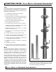
CHAPTER SEVEN: SELECTING & INSTALLING GUY WIRES C onsistent, safe support of antenna installations over 10 feet above the uppermost wall bracket or roof mount depend on how well the guy wires are installed. The correct installation procedure is relatively simple. However, only the best quality materials and careful installation will provide sturdy, safe, long-lasting support. Fig. 7-1. The materials and hardware needed for guying a standard three-wired guyed installation.
The guy wires are attached to the upper half of each mast section with guy ring and clamp. The ring and clamp are fitted to the mast before the antenna is attached (Figure 7-4). The mast ends of the guy wires are run through holes in the guy ring. The wire then is wrapped around itself at least six times (Figure 7-5). The final tightening of the guy wires is accomplished by rotating the turnbuckles with a screwdriver.
CHAPTER EIGHT: ANTENNA ROTORS A rotor or rotator is a mast-mounted, motor-driven device (Figure 8-1) that permits the TV viewer to conveniently rotate (orient) the outdoor TV antenna in any direction. It is started and stopped by a manually operated control unit (Figure 8-2) that is placed indoors near the TV set. A multi-conductor wire carries the power and control signals from the indoor control unit to the mast-mounted drive unit.
Fig. 8-3. Connecting the rotor wire to the drive unit of the rotor. The “reference wire” is either wider or is a different color than the other conductors. Connect it to terminal No. 1. Connect the middle wire to terminal No. 2, and the third wire to terminal No. 3. If you use four or five-conductor wire, attach the third, fourth, and fifth wires to terminal No. 3. (Figure 8-3 shows the rotor wire connections to the drive unit.) The wires must not touch each other or the housing after they are connected.
As previously mentioned, a loop of transmission wire must be left between the antenna and the drive unit to prevent the line from becoming tangled in the antenna or otherwise restricting rotation. Be sure the housing of the rotor drive unit is properly aligned with the antenna terminals. To properly align the rotor with the antenna, always install the drive unit with the front (the side of the unit without fixtures), facing away from the antenna terminals (Figure 8-8).
CHAPTER NINE: ANTENNA-MOUNTED AMPLIFIERS A introducing more noise. However, this will not always solve the problem especially if the received signal is exceptionally weak. mast or antenna-mounted amplifier (preamp) is used primarily to eliminate “snow” on the TV screen. “Snow” (Figure 9-1) is actually electrical noise that is generated by the TV receiver and other electrical devices.
Although the ideal preamp usually is the one with the lowest noise figure and the highest gain, compromises sometimes must be made. If very strong local signals are present, a preamp with a high input capability must be used. A high input capability will prevent the strong local signals from overloading the preamp. However, a preamp with a high input capability has a slightly higher noise figure. Coaxial cable should be used with all preamp installations.
CHAPTER TEN: MULTI-SET RECEPTION M any homes have more than one TV set. Others have at least one FM radio receiver and VCR. Consequently, the installer often must use an antenna system that feeds the received signals to two or more receivers. This is called multi-set reception. Supplying the signal from one antenna to two or more receivers requires the use of special devices that prevent problem-causing interaction between the TV receivers.
Before attempting multi-set reception with passive devices, use a field-strength meter to measure the signal strength at the receiver end of the main transmission line. If it is less than 2000 microvolts (uV) and you need to feed three sets, you will have to increase the signal level. To do this, you will have to use one of the following methods: • • • • A higher gain antenna A mast-mounted preamplifier (preamp) Both a higher gain antenna and a preamp An Amplified Coupler Amplifiers Fig. 10-4a.
TV-FM SPLITTER Fig. 10-5. A diagram of a typical medium-sized home MATV system.
CHAPTER ELEVEN: TROUBLESHOOTING Antenna Systems Interference Trailing Ghosts There are times when despite all the careful planning and attention you’ve given an installation, outside interference still shows up on the TV screen. Some of the most common interference problems and their solutions are discussed in this chapter. Trailing ghosts are usually caused by TV signals that bounce off hills or tall buildings.
INTERFERENCE Adjacent Channel Interference Though it is not uncommon, often the signals of one channel will show up as interference on the channel next to it (Figure 11-4). This usually happens only when the receiving antenna is midway between the transmitter towers of two adjacent channels. Because the frequencies of the two channels are relatively close, the TV tuner amplifies both the desired channel signal and that of the adjacent channel.
CB and/or Ham Radio Interference Strong, local signals transmitted by Citizens Band (CB) or Amateur Radio (Ham) operators can cause a picture to roll, fade, or disappear completely. Sometimes, horizontal lines appear on the screen (Figure 11-7) and the voices of the radio operators are heard in the TV audio. appliances such as furnaces, mixers, hairdryers and humidifiers are principal causes of electromagnetic interference.
GENERAL TROUBLESHOOTING GUIDELINES When servicing an existing system, be sure to check the strength and quality of the signals being received and the condition of the equipment being used. Measure signal levels with a field-strength meter. Check general picture quality with a TV set you know is operating correctly. You may find that an improper installation or a change in reception conditions is causing problems that can easily be solved.
CHAPTER TWELVE: SELLING & INSTALLING SYSTEMS S elling and installing TV antenna systems has been, and will continue to be, a profitable business for competent installers who understand and apply proven business management and operating principles. A few years ago there were predictions that community antenna television (CATV) systems would eventually eliminate the need for home TV outdoor systems.
Business Bank Accounts Establish a business checking account, preferably at a bank with which you are familiar. Pay as many business expenses as possible with checks drawn on your business account. This will help ensure complete records and receipts for business expenses. As soon as your business income permits, establish a business savings account.
If you use only the best quality antennas, masts, hardware, and related components, you should have complete confidence in your products. If you plan and install each system with care, you should have complete confidence in its ability to do what you say it can do. This confidence should make selling a comfortable experience, because you know that your customer will be getting a quality product that will perform as you say it will, and is being sold at a fair price.
As an installer, you can buy antennas and related materials at a sizable discount. You can reasonably add 30-40% to antenna prices and sell them to the retailer. He in turn, sells antennas to his customers with whatever additional markup he desires. In this manner, the retailer makes a profit without having to stock merchandise, keep an inventory, or use up valuable floor and warehouse space. This is “gravy” for him and more profits for you.
Encourage the retailer to display one or more antennas on his sales floor. A good in-store display like that in Figure 12-1 will encourage customers to ask about additional equipment. Try a window display too. Antenna distributors and manufacturers often can supply a large assortment of in-store display materials. Channel Master, for example, offers an attractive line of “Do-It-Yourself” displayed products. Examples of these are shown in Figure 12-2. Sign up as many retailers as possible.
A well-chosen business name is important. Some businesses spend a large amount of money to develop a name and logo. (A logo is the stylistic way your company name is printed.) As a new businessman, you probably will not be able to afford to spend much money developing your company name and logo, but you should invest some thought, time and effort in it. When you decide on a name, work with a local artist to develop a logo.
GLOSSARY OF ANTENNA SYSTEM TERMS Acrylic Insulator–A plastic material that is used to weatherproof outdoor antenna system connections. It is applied in liquid form, typically by aerosol can. Alignment Bearing (rotor)–A ball bearing-equipped guy ring that is slipped onto the antenna mast above the rotor to permit guying of the mast section rotated by the rotor.
Element, Antenna–The small, hollow metal rods of various lengths that are attached (usually perpendicularly) to the main horizontal support member (boom or crossarm) of the antenna. The element at the rear of the antenna (called reflector) is usually the longest. The element that actually feeds the intercepted signal to the antenna output is called a dipole.
Lug, Terminal–See Terminal Lug. Mast, Antenna (TV)–A vertical section (or sections) of tubular steel or aluminum on which the antenna is mounted. Most sections typically are available in 5 and 10 ft. lengths. Matching Impedance–See Impedance. Matching Transformer (TV)–See Balun. Microvolt (uV)–One millionth of a volt, or 0.000001 volt. The strength of the signals in a TV antenna system is expressed as so many microvolts (uV).
Signal Mismatch–A condition in which an antenna system delivers signals whose strengths and general quality vary. This usually is the result of incorrectly installed signal-distribution components. (See Interaction, Signal.) Tunable Trap–A small device that can be tuned (adjusted) to eliminate any one of the number of frequencies within a band. Tunable traps are frequently used with preamps, to eliminate a particularly troublesome signal.
Hyper Band Picture Carrier MHz Channel Number Frequency Band MHz Picture Carrier MHz 54-60 60-66 66-72 76-82 82-88 88-108 120-126 126-132 132-138 138-144 144-150 150-156 156-162 162-168 168-174 174-180 180-186 186-192 192-198 198-204 204-210 210-216 216-222 222-228 228-234 234-240 240-246 246-252 252-258 258-264 264-270 270-276 276-282 282-288 288-294 294-300 300-306 306-312 312-318 318-324 324-330 330-336 336-342 342-348 55.25 61.25 67.25 77.25 83.25 (100.00) 121.25 127.25 133.25 139.25 145.25 151.