
Installation guide


ANTENNA ROTORS
24
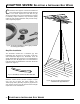
As previously mentioned, a loop of transmission wire
must be left between the antenna and the drive unit
to prevent the line from becoming tangled in the
antenna or otherwise restricting rotation. Be sure the
housing of the rotor drive unit is properly aligned
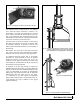
with the antenna terminals. To properly align the
rotor with the antenna, always install the drive unit
with the front (the side of the unit without fixtures),
facing away from the antenna terminals (Figure 8-8).
This will allow the transmission line to be looped into
a snap-on standout approximately 3”-4” below the
rotor on the rear of the drive unit housing (the side
with clamps for the main lower mast).
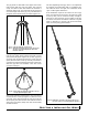
When the rotor and antenna have been properly
aligned, tighten the clamps holding the top (antenna)
mast and run the rotor wire down the main mast. The
best way to do this is to use 7” standouts or in-line
double standout; (for transmission line and rotor
wire) mounted with nutbuckle and strap, spaced
equal intervals along the main mast. (Taping the rotor
wire to the mast may be acceptable for some smaller
installations.)
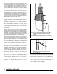
Coaxial cable should be used with all rotor installa-
tions to void interaction that can occur between rotor
wire and 300 ohm twinlead. If you must use twinlead,
keep it at least 3” away from the rotor wire and mat at
all times. Again, the use of in-line double standouts
before the rotor (Figure 8-9) is recommended.
The rotor wire should be connected to the control
units in the same manner as it was connected to the
drive unit. The reference wire is connected to terminal
No. 1, the middle wire to terminal No. 2, and the third
wire to terminal No. 3. Leave enough rotor wire at the
control unit to permit movement of the unit to any
point in the room.
The final step in a rotor installation is to synchronize
the control unit with the drive unit. For fully
automatic control units, turn the control dial (knob)
clockwise to the due north setting and allow the
antenna to rotate until the control unit stops it. Then,
turn the dial counterclockwise to due north, again
allowing the antenna to rotate until the control unit
stops it. The installation is now synchronized.
The process is the same for semi-automatic control
units except that you must depress the clockwise and
counterclockwise buttons one at a time until the
antenna stops at north in both rotational directions.
Anytime you believe the installation is out of
synchronization, repeat the above process.
Control units come with small adhesive stickers that
can be placed on the control unit housing to indicate
the best antenna position for each channel. When you
have determined the best antenna position for a
channel, place a sticker with the channel number in
the appropriate spot on the control unit housing. The
rotor installation is now complete.
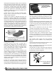
Fig. 8-7. A loop of extra transmission line must be left between
the antenna and the drive unit to prevent the line from
tangling in the antenna or otherwise restricting its
rotation.
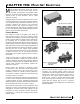
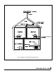
Fig. 8-8. Always install the drive unit with the “front” facing away
from the antenna output terminals.
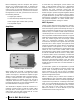
Fig. 8-9. In-line double standouts should be used to keep the
twinlead and the rotor wire separated.They are not
necessary for coax.