Technician Manual Version 3.
Table of Contents 1.0 INTRODUCTION ........................................................................................................................................................... 5 2.0 EYEON SERVER: QUICK START GUIDE............................................................................................................... 6 2.1 2.2 2.3 2.4 2.5 2.6 2.7 2.8 ACCESSING THE EYEON HOME ADMINISTRATOR SCREEN ...........................................................................................
4.20 UPS: APC (140001) .................................................................................................................................................. 54 4.21 POOL/SPA: JANDY AQUALINK POOL (150001) ........................................................................................................ 55 4.22 TOUCH SCREEN: WINXP PRO 400MHZ (100001)................................................................................................. 56 Pre-wiring requirements...................
9.1.1 EyeOn Remote Basics ....................................................................................................................................... 124 9.1.2 System Code Selection Procedure..................................................................................................................... 125 9.1.3 EyeOn Remote Control Specifications.............................................................................................................. 125 9.2 EYEON REMOTE PROGRAMMING ..
1.0 Introduction Follow the steps outlined in this EyeOn Technician Manual to get your system up and running. Use the Technician Manual and Quick Start Guides to help you through the initial setup process. Begin the setup process by installing all hardware that is included in your system. Please referrer to the manufacturers’ specifications and instructions for installing specific subsystems. Some subsystems may require pre-configuration. For example, the JDS Infrared Xpander by default is set for 4800 BPS.
2.0 EyeOn Server: Quick Start Guide Before configuring the EyeOn Server, we recommend connecting all subsystem (audio, video, climate, etc.) hardware first. Please read the specific sections of this manual which apply to the devices that are being configured. Some devices require special configuration and will require additional setup 2.
User Name: admin Password: ^eyeauto! 2.2 Configuring the EyeOn Server Now that you have navigated to the EyeOn Home Administrator screen, start setting up the EyeOn Server. 1. Click on the Profile link to bring up the following screen: 2. Use the drop-down boxes to choose the correct model number for each subsystem. 3. Click the Next button at the bottom the screen to save changes. Notice that the Profile screen also displays the default Unique Name.
2.3 Activating the Subsystem Links Once the Profile screen has been configured, the server must be updated by performing the following steps: 1. Click on the Setup link. 2. Click the Update Server button. 3. Click the Event Log link. 4. Click Detect Hardware link. Since this is the first time the server will be detecting the hardware, this process can take up to 20 minutes. Once all hardware is detected, future boot times should be anywhere from 2 to 5 minutes.
2.4 Configuring the Subsystems Now that the hardware has been detected, the Rooms link should be configured. Enter in the name of each room that contains a touch screen or a subsystem device; also enter a number for the sort feature. We recommend using increments of five (5) so as to leave space to add additional rooms later. The subsystem links (Audio, Video, Security, etc.) should be active. 1. Click on the first active subsystem (i.e. Audio) 2.
2.5 More about the Setup screen Though there are several settings under this category, only configure a Username and Password to get started (refer to the EyeOn Technician Manual for details about the remaining options). The purpose of this setting is to give the home owner their own username and password for remotely accessing the EyeOn User Screen. This username will only allow the end-user to access the EyeOn User Screen, it will not allow them access to the EyeOn Home Administrator Screen.
If changes are made to any category, other than Profile, click the Update Server button followed by clicking the Soft Server Reboot button. When a Soft Server Reboot is performed, the server will stop responding for up to 59 seconds. Subsequently, the touch screen will also reboot with the new configuration changes. Warning! Performing a Soft Server Reboot will cancel all commands. For example if you are programming lights while you hit Soft Server Reboot the programming process will be canceled.
2.8 About User Website Access Accessing the EyeOn system remotely is an important feature of the EyeOn Automation system. This can be achieved using the unique URL that was created for your system. If the router is not setup the default IP address is http://192.168.130.90/website/ or https://192.168.130.90/. However, this will only allow you to access the User Website and Administrator setup options from your Local Area Network.
3.0 EyeOn Touch Screen: Quick Start Guide 3.1 Introduction The EyeOn Touch Screen is the perfect compliment to the EyeOn Automation Server and gives the homeowner convenient access to all of the functionality EyeOn Automation has to offer. With our touch screen, the homeowner will have convenient control over lighting, whole-house audio, video distribution, climate control, surveillance, and security systems, just to mention a few.
3.3.1 Method 1: EyeOn Touch Screen not Connected to an EyeOn Server Applying power to the EyeOn Touch Screen before connecting it to an EyeOn Server will result in the following error message: EyeOn could not connect to the server, would you like to change your IP settings? ‘Yes’ ‘No’ Please select ‘Yes’ and the Settings menu will appear. Figure 1 To change the touch screen IP address: 1. Select the Change button ( you will redirected to the Control Panel) 2.
Figure 2 3.3.2 Method 2: EyeOn Touch Screen Connected to an EyeOn Server The Control Panel can also be accessed from the EyeOn Touch Screen’s interface by using the Screen-Lock keypad or the Security keypad. Once either has been evoked, simply type 039366 to access a “hidden” menu (Figure 3). Figure 3 Select the Settings button to display the Settings screen as shown in Figure 1.
3.4 Choosing a mounting location Before starting, there are a few things to take into consideration when choosing a location for the EyeOn Touch Screen: • • • Do not install the unit in a location that will expose it to direct sunlight at any part of the day. Avoid contamination from insulation by installing touch screens in non-insulated interior walls. Consult a licensed electrician to determine if a particular location is safe and in compliance with state and local electrical codes.
Figure 5 3.7 Terminations Before terminating the communication and power cables, take a moment to get familiarized with the connection points on the touch screen, shown in Figure 6. Figure 6 1. Start by crimping a connector onto the Ethernet cable. Performing this step first is very important, since it won’t be able to set the touch screen aside once the power has been connected. Note: EyeOn recommends using the T568-B or T568-A standard.
4. After ensuring that each terminal has been loosened enough to accommodate the wire, insert and secure each wire into the touch screen’s terminal block, as seen in Figure 7. 5. Tug each wire after they are tightened to insure that they are secure. Figure 7 6. Insert the Ethernet connector into the touch screen’s Ethernet port (shown in Figure 6). 3.8 Mounting the touch screen Attach the power and the network connections that were discussed in the previous section.
3.9 Remote Access The EyeOn Touch Screen is accessible through Windows Remote Desktop. To access the touch screen remotely follow these steps: 1. From the Start menu select Run. 2. Type in mstsc.exe then hit Enter. Figure 9 You will be prompted to enter the IP address of the touch screen you want to access remotely. After you hit Connect enter the Username and Password below.
4.0 EyeOn Hardware Setup 4.1 AUDIO: Nuvo Concerto and Grand Concerto System (010001) The following information is only meant to supplement the manufacturer’s documentation and is based on the assumption that the Installer is already familiar with installing and configuring the Nuvo Concerto, Grand Concerto, and keypads: 4.1.1 System Overview The following diagram is a great illustration of a fully functional system.
• The Nuvo Concerto audio system requires internal programming for the system to work with the EyeOn Server. 4.1.3 Suggestions • First, you will have to know which rooms in the house have speakers. If you have one area that is close together sometimes it is better to combine four speakers into one zone, but never more than four. • You should have all the wires labeled for each room. • Remove the green terminals from the back of the Concerto Unit.
After you have decided how you are going to have the system laid out you will need to download the Nuvo desktop software to your computer. Download Version 1.6 by using your EyeOn Technician CD with filename Concerto_V1_60_Full.zip. To begin, you will have to create a new configuration or if you have already started one you can load an existing file. The IR Library section is used to control other devices that might be linked as a source on the Nuvo, for example, a CD player.
control that source. If you have no keypads then you can skip this step. (More information for setting up IR devices is located in the Integra DPC-8.5 section on page 30.) Use the Source section to set up your sources. If you are using the EyeOn system as an intercom, doorbell, or for audio feedback Source 6 should be set to Intercom System. The Model and Type are just generic. If you are using a CD or DVD device, you can add this to the system by selecting the make and model.
(Notice the gain, some devices put out less output than others. You can use this to have Nuvo broadcast the source at a louder volume.) If you are using the server intercom system, please set source 6's gain to +12.50. If you are using a FM/AM/WX tuner, we recommend using +1.25. If you are using a XM tuner, we recommend using +4.00. If you are using the DPC 8.5, we recommend using +1.25. If you want to utilize Macros, please see the Nuvo Concerto Owner's manual.
Example 1: (pictured below) If you are using the Audio feedback or doorbell you must use Zone 16 for the System Master take over for the intercom. Make zone 16 only have access to source 6. Here zones 1-6 are normal zones, zone seven is output to the input of a home receiver in another room and a slave of zone six, which is a near by room. Zone 16 is the system master, 20 is a slave zone to Outside (Zone 5). Two controllers are used, one inside and one out, both serving the same functions (Zone 5 and 20).
4.2 AUDIO: Russound System (010003) The Russound audio system does not requires internal programming for the system to work with the EyeOn Server. You will have to know which rooms in the house have speakers to program the EyeOn administration screen. If you have one set of speakers that will be installed in close proximity to another, it is better to group these four speakers into one zone.
Display Preference Mode (3.DSPLY PREF) This mode allows you to choose how XM channel information will be displayed on the keypad and tuner. Appropriate button presses access the next or previous preference item. Note: For any display configuration, the artist’s name and song title will scroll before the display returns to the designated display format. Channel Number (CH NUMBER:) This selection displays the channel number only (e.g., XM070, XM103).
From here, you will be on the Configurator screen where you will need to select which Nuvo device you have. Below is an example of what this setup screen could look like. You must specify what source the tuners are hooked to. We also recommend using the “Automatically Turn Tuner On when power is applied” checkbox. All presets will be setup from the EyeOn web-based software. To do this, you must first set the presets to a default station.
For the XM tuner, you should simply setup the presets for XM1. At this time, it is good to save the configure file somewhere so you can work on it later as needed. You will need to download the information into the tuner. If you have an error message while doing this try power cycling the tuner. Also try just doing side A then side B one at a time. After you have finished the installation, there is one more necessary step for the Concerto system to communicate with the T2 tuner.
4.4 AUDIO: Integra DPC 8.5 (030001) There is no software to communicate with the Integra DPC-8.5, six-disk DVD player. All that is needed for the EyeOn system to communicate with this device is to plug it into the server with a RS232 cord. If you are using any of the supplied Nuvo keypads, you must program in the IR commands to give the keypad the ability to start, stop, skip, etc. To view the DPC-8.5 Owner's manual use your EyeOn Technician CD to view the file DPC85. 4.4.
4.5 MEDIA SERVER: Dell Optiplex 755 (130001) The EyeOn Media Software was designed to enable communication between the Dell Optiplex and EyeOn System. This must be connected over CAT 5 to the network. The Media Server communicates over TCP/IP.
4.6 VIDEO: CHANNEL PLUS SVS-88 S-Video Matrix Switcher (040001) There is no software to communicate with the CHANNEL PLUS SVS-88 S-Video Matrix Switcher. All that is needed for the EyeOn system to communicate with this device is to plug it into the server with a RS232 Null Modem cable. This is not a regular RS232 cord. It is also recommended that the Channel Plus be hooked into ttyS0 (The onboard serial port). The SVS-88 has eight inputs and eight outputs.
4.7 VIDEO: Key Digital Fatboy Switcher (040002) There is no software to communicate with the Keydigital Fatboy Switcher. All that is needed for the EyeOn system to communicate with this device is to plug it into the server with an RS232 cable. This is a regular RS232 cord The Fatboy has eight inputs and 4,8,12,16,etc outputs. When hooking your audio and video cables to it, you must remember which inputs are in which number and which outputs are where. We recommend writing this down as you do it.
4.10 SECURITY: ELK M-1 (050001) Hooking up the Elk security system is the most in-depth part of the EyeOn installation process. The Elk controls the in-house security system, opening and closing garage doors, turning touch screens on and off, routing power to different devises, intercom systems, pool alarm, etc. The following files can be found on your EyeOn Technician CD. For the ELK M-1 installation and programming manual view file M1_Installation&Programming_Manual.
The Serial Number is located on the bottom of the M1 board. The RP Access Code is very important. If you lose the RP Access Code you can not make changes to the ELK programming. Make sure you write down this information. After you fill out all the customer information and connect the RS232 cable, choose the connection icon and Direct Using COM1 (Which ever port you have it connected to) After you are connected you will need to Upgrade the Firmware.
This will take several minutes to upgrade. After the program is updated you will not be able to reconnect for a few minuets because the EEPROM is upgrading internally. Now that you have upgraded the system it's time to setup the remaining information associated with the system. Start by choosing the Users Tab. Here you will setup each user's code. Most houses will only have one. You will have to contact the home owner to find out what code they'd like to use.
After you have setup the Area's you will need to setup the keypads used in the house. Before setting up the keypads you will have to enroll them into the system. Each keypad will have an assigned address. From the factory all keypads are set to address one. Valid keypad addresses are 1 to 16. The first keypad on the system (Keypad 1) is automatically enrolled upon power up. Each additional keypad must be assigned a unique address and then manually enrolled from Menu 1 - Bus Module Enrollment.
The ELK M1 Main board has 16 zones built on. Expanders can be added to this unit during install. If there are more than 16 input zones, or you are using a wireless card, right click on the inputs link and choose New Input Expander or New Wireless Expander.
If you are installing a door sensor, use definition 01 and type normally closed. If you are installing a motion detector, use definition, 04 and type normally closed. If you are installing a glass break detector, use definition 01 and type normally closed. If you are installing an outdoor motion detector, use definition 16 and normally closed. If you have any indoor sensors but shouldn't activate any alarms, set them to definition 16 and normally closed.
Once you have completed the zone setup, move to the global settings. G01-05 can remains default G06-G10 remains default G11-G12 should be set to 4 digits unless the home owner would like a 6 digit code G13 remains default G14-G18 remains default G19-G25 remains default G26-G28 If you have installed an outdoor siren to output 2, choose siren output.
*The local programming code is set to 172839, this should be changed so other installers can not access your system at the keypad level. If you are having problems with the outdoor siren, you might have to switch the wires going into the ELK output 2. Make sure you save the configuration file so that you can access it later. Once you have completed the entire settings configuration you are ready to update the ELK system. Choose the Send/Rcv icon on the toolbar to send your data to the ELK system.
4.11 SECURITY: WebRelay (170001) WebRelay is an electro-mechanical relay with a built-in web server. It can be controlled via the Internet or a local intranet. It is very simple to set up and use and has many features. There are 3 types of WebRelay devices that are integrated with the EyeOn Automation system: WebRelay, WebRelay Dualm and WebRelay Quad. To begin setup on the WebRelay hook up unit to power and network only. Next setup a computer on the same network using an IP address of 192.168.1.
4.12 CLIMATE CONTROL: RCS TR40 (060001) Use file TR40 Owners Manual on your EyeOn Technician CD to view the TR40 owner's manual. Use file TR40 Remote Temp Sensor Manual on your EyeOn Technician CD to view the TR40 remote temperature sensor install manual. (OS21) The TR40 has software that can communicate with it directly. This software is not needed to setup the TR40 to work with the EyeOn system but might want to be used for trouble shooting.
Scroll down until you are on the network address and hit the + and - keys to set each address uniquely, start with Address 2. Note: After you have setup the Network Address you must set the Auto Send Mode to YES or you will not get feedback from the system when a user makes a change at the remote level.*** For advanced diagnostics you can view file TR40 Serial Protocols on your EyeOn Technician CD to get a list of the RS232 protocols for the TR40.
4.12 SURVEILLANCE: URL (070001) Using this feature will only allow for a direct link to the web based interface of the DVR system. You will include the URL in the admin setup section. All setup must be configure on the DVR itself and is not supported by EyeOn. 4.13 SURVEILLANCE: PC DVR (070002) The PC DVR comes preinstalled from the EyeOn Service Center. The PC DVR communicates to the server though http commands sent by the Linux server. No RS232 protocols are used.
4.14 LIGHTING: Insteon (080002) Use your EyeOn Technician CD to view the following files. For Insteon SwitchLinc V2 Dimmer User's Guide view file Insteon-SwitchLinc. For Insteon SwitchLinc V2 Relay User's Guide view file Insteon-SwitchLinc-Relay. For Insteon KeyPadLinc V2 User's Guide view file Insteon-KeypadLinc. For Insteon KeyPad Linc Labels view file Insteon-KeypadLinc-Labels. For LampLinc V2 User's Guide view file Insteon-LampLinc.
4.15 LIGHTING: Lutron (080003) To view the Lutron RA-RS232 setup guide please view the PDF on your EyeOn Technician CD. Lutron must first be installed in place of all the light switches you would like to control. The EyeOn system will only add direct control to each light in the house. All sensors can only be accessed at the switch level. Once you have installed the lights throughout the house, it's important to setup at least one repeater. The RA-RS232 will communicate directly with the repeater.
Then, you will walk around the house and turn on or off every light switch you wish to control. When the light switch is turned on or off, it should blink two or three times to show you that it was accepted. After you have programmed all light switches into the repeater you can press and hold the ACTIVATE CONTROLS button until the green LED turns off (this takes about three seconds).
4.16 LIGHTING: Leviton (080004) This only works with the Dimension D3208. This is not for the wireless system. The first thing you most do is set the time on all the Dimensions D3208 or the units will flood the network. To do this you will click the menu button and scroll up to the Time Wizard. Once here go through the steps and setup the time. HAI?? Then you will need to setup a panel ID for each Dimension D3208. Go to Menu then setup wizard. Do the basic setup.
4.17 LIGHTING: Leviton Z-Wave (080005) This works with the Vizia RF System You must setup all lights with the controller. We recommend the RZCPG. Begin by setting up all of the lighting devices. Menu>System Setup>Install Checklist>Include Dim/Switches> Then you must go through and add each light. We recommend setting up a spread sheet with the room, light name and the node number. To save time you do not have to create all the names on the RZCPG controller as long as it is documented.
4.18 IR: JDS (090001) To download the User Manual and get a list of the RS232 protocols view file JDSManualAndProtocols on your EyeOn Technician CD. This device must be changed over to Serial Mode before connected to the server. 1) Remove any static charge from your hands by touching a piece of metal. 2) Remove the two Phillips head screws on the rear panel of the IR-XP2 and carefully slide out the circuit board. 3) Locate the four jumpers just behind the RS232 jack on the edge of the circuit board.
4.19 IR: Ocelot (090002) Hook up the Ocelot to the server with RS232. You can add one ADICON 2500 SECU16-IR module to the system. This will give you up to 16 different IR ports. You need to make sure you address your SECU16-IR module before you start. It needs to be addressed as module 0. The addressing will probably happen automatically. If the expander module is not working you must load the software that came with the Ocelot and click on “attach to controller” and update the module.
4.20 UPS: APC (140001) The APC must be hooked up to the EyeOn sever through a USB cord to enable a communication flow.
4.21 POOL/SPA: Jandy Aqualink Pool (150001) There is no configuration needed on the Administrator screen for the Jandy Aqualink Pool. The Jandy controller: however, does need to be hooked up to the EyeOn server using RS232 connection.
4.22 TOUCH SCREEN: WinXP Pro 400MHz (100001) All Touch Screens come from the EyeOn Service Center preconfigured. An IP is already set and each screen will act as a computer on the network. Touch Screens should be installed in the wall with the proper mounting bracket and hooked up properly. A power wire and Cat5 cable (hooking into the network hub in the server room) should be all that is connected to the screen. EyeOn’s Touch Screen is a low-voltage device requiring a 24VDC power supply.
Start by crimping a connector onto the communication cable, using the T568-B standard. (Note that this wiring standard must also be used at the switch or router.) Performing this step first is prudent, since you won’t be able to set the touch screen aside, once the power has been connected. Prepare the 16/3 power cable by stripping away 1.25” of the outer insulation. Next, strip 1/4” inch of insulation from each wire.
4.23 VIDEO HARDWARE: JVC RS232 DVD/VHS You must turn off power saving mode. Make sure you can see the video.
4.24 Access Control (120001) A computer should be pre setup before it goes on site with the RFID Badge Software. You will need to set the IP address to be on the local network for the computer. We have set the IP by default to 192.168.130.9. The computer is setup to communicate with 192.168.130.90 by default. If you need to change this then: Navigate to the following directory C:\Program Files\Hitcents\IDBadgeCreator\ Then load Hitcents IDBadgeCreator.exe.
On each panel you most address them starting from 1 and going up from there. The first 5 dip switches are used for addressing. These are setup in binary format. So 1 on all the rest off = 1. Please refer to the manual for a digram. Troubleshooting: If the card is not reading at all then the processor might be locked up on the NStar. You need to do a full reset. Look in the NStar manual for instructions. If you card is reading sometime you need to terminate the wires better.
5.0 Wireless Configuration If you are using Linksys Wireless Access Points these steps can help you below. (These steps can change depending on the firmware version). If you are using a different model please adapted these steps to your setup. Configure wireless AP points (one at a time). Make sure only one is plugged in at a time. Set computer IP to 192.168.1.2 255.255.255.0 Navigate to http://192.168.1.245 Default password is admin.
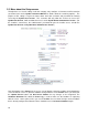
6.0 Accessing Administrator Screen You will need an internet browser to access the secure administrative setup screen at the following URL: https://192.168.130.90/admin/ or http://192.168.130.90/website/admin/. You will be prompted to enter your dealer user name and password to access the EyeOn system. You will then see the EyeOn Automation Administration login page. Just re-enter the same user name and password to login as an administrator.
After logging in, you will be presented with a welcome screen and navigation options for the EyeOn system. This is where you will set up each component of the system the customer will be using. This will start your setup for the EyeOn Automation System you are about to configure. By following this step by step process you should be able to install all the server software as well as set everything up to a live system.
6.1 Profile The profile tab is where you will indicate the hardware that the customer has chosen to use with their EyeOn Automation system, so that the software program knows to relay to each piece of equipment. The Profile screen displays your default Unique Name, which is often time referred to as UName. The UName is a unique identifier (in this case, TESTBOX) for remotely accessing your system, so that you can simply enter https://testbox.eyeonautomation.com to log on to your EyeOn server.
Next to each device select the device that corresponds with the individual EyeOn system. Tuner 2 is used if there is a separate tuner involved in the IR Send is only used if there is more than one IR device in your EyeOn system. Note: You must refer to the system hardware or the customer estimate of equipment specifications.
6.2 Rooms This is where you will identify each room that has EyeOn components to control. Setting up rooms: You will need to add a room on this screen if the room contains any of the following: • touch screen • audio • video distribution • lighting Name each room and give it a sort number. The sort is the order in which the rooms will appear in the EyeOn control menus. The lowest numbered room will be at the top of the list and the highest numbered room will appear at the bottom of the list.
added later, all rooms might have to be renumbered. As in the illustration above, sort the rooms using a range of numbers to avoid having to renumber rooms later. Be careful to type the room name correctly, this is how it will appear on the customer’s screens. Also be aware that there is no length limit for naming the room. You should make sure the name is not too long to fit on the button. Sometimes this requires trial and error with a few names to determine what will work.
6.3 Audio Use the audio tab to specify audio sources with their respective remotes. Also enable keypads with their respective zones and set announcement volume levels. (Different Audio system page will look a little bit different. For example on the Russound page you will not see keypads) Identify each audio source with a descriptive name. Be sure to select if the source is enabled or disabled and specify if the source has a remote or not.
6.3.1 Nuvo The NoVo requires you to put which keypads are enabled. You will need to choose to enable or disable keypads. Choose if there is a keypad or not. Then select the room the keypad is in. If this is a line level source please select this room has a keypad. 6.3.2 Russound Sound If you would like to have audio feedback on the Russound please label the source name SERVER. This will tell the server that is the audio feedback source number.
6.3.3 Media Server If you have a Media Server hooked up to your system and registered in the profile screen you will see the Media Server Text box at the bottom of the Audio screen. You must enter in the IP Address of the Media Server and the port number in the format that is specified. The default IP address and password cannot be changed on the Media Server. Select Next when you are done making changes to the audio setup.
6.4 Video This screen is used to manage the video inputs in your EyeOn System through the use of Video Distribution. From the Video Menu, name the inputs in your Video System (Example: SATELITE or DVD) make sure they match to the actual inputs in your video distribution component. Then select the Remotes from the drop-down box correspond with each of the devices. Make sure device is set to “Enabled” to allow for video distribution. If you have not setup the remote for the Inputs please see Managing Remotes.
6.4.1 - Managing Remotes Managing remotes is used to control input and output devices. You can control them though RS232 and IR. For example, most TV’s have infrared capabilities which allow you to control different functions of the TV through IR commands. For better results, devices that have RS232 support can be controlled though RS232. At the top of the Video screen select the “Manage Remotes” link. Next select Add Remote. Select IR or RS232 6.4.2 For IR Name the Remote (example: LG DEN or INTEGRA).
Hit ‘Next’. If you have already learned the IR codes then continue, if not go to section Learning Codes. Select the appropriate code from the drop down box. Select the Port. * if you are unsure which port to use Click on the ‘IR’ link at the top of the screen to see a list of devices and corresponding ports. You can also choose to run a mood by selecting “RUN MOOD”. You will be required to enter in the mood number in the box below where it says “RUN MOOD.
Scroll down to the “Send IR Command Unit 1” list. Hit “Add New IR Send Unit 1” link at the bottom of the screen. Name the IR (example: CAB-CHU or DVD-PLAY). Aim the remote at the IR Expander and press the button you should see a green light. You might need to wait a few seconds to hit the remote button. You must repeat this process for all codes. Hit “Continue” to save the command. After you learn all of the codes continue with the IR Remote Managing process.
6.4.4 Configuring RS232 Begin by naming the remote. The remote will only be visible from the Touch Screen and PDA. You will not be able to see the remote on the web-based software or mobile phone. Device Next select the device you would like to control with the remote. Use the drop down box to see a complete list. If the device is not in the list then EyeOn is not integrated. Please refer to the Hardware Integration form on the resource center. Com Port The com port is used to communicate with the device.
6.4.6 Volume Overrides If you are using a sound source other than your TV, for example Surround Sound, you will need to program in moods to adjust the volume on your Surround Sound using your TV remote. To get the mood number, see the Getting Mood Number section. Enter in the appropriate mood numbers and then hit “next” to save the remote. If you have not set up the moods continue to the Setup Volume Moods Section below. Setup Volume Moods Select “Setup” from the web based menu.
Another option is to use Remotes tab to add the commands. You can only do this if you have programmed in the remote though Managing Remotes. This will allow you to adjust the volume of RS232 devices. Depending on how quickly and drastically the volume changes per command, you may have to add the command to the mood a couple of times and then set a wait timer. Different devices may vary; use trial and error to determine the best fit for your system and device.
Getting Mood Number To get the Mood Number scroll your mouse over the “Activated” or “Deactivated” link next to the Mood you want. The number is displayed in the bottom left hand corner of the Status Bar, see screen shot below. The Mood number is the 4 digit number that is circled in the example above. The Mood number is unique to each Mood.
6.4.7 Advance Video Setup Use the “Advance” link to set up the advanced source options. This screen allows you to setup Moods to override normal video destitution functions. For example, you might want to set up a mood that turns the TV to the ‘on’ position and to the correct input, lowers the lights and starts a DVD all at the touch of a button. This will save you the hassle of having to turn on each device individually.
mood to your source to adjust the video distribution and any other functions you would like to perform. See “Moods for Advance Video Setup” to set up Moods. Once you click Add Source there are two options; New Source and Override source. An example of a source override would be selecting a device that is hooked up to the Video Distribution (example: Satellite and Cable Box). An example of a new source would be a Local Source such as a DVD player that is actually hooked up to the TV in the room.
Lock Options There are 2 checkboxes that give you the option of locking the volume and power functions. Selecting the first check box will lock the volume and mute button on all of the sources. This means that no matter which remote you are using the volume will be adjusted on the TV or surround sound rather than adjusting volume on different sources such as a cable box or satellite. The power lock uses the same concept.
In the example above we begin by first sending a command to switch the Video Distribution to the correct input (Satellite) The next thing we do is switch the input on the TV to satellite. This will commentate a TV that is already in the On position. Then we power on the components in the selected room (example: TV) incase they are not already on. Toggling can be an issue, to work around this, use discreet IR commands to set up two separate buttons for on and off.
6.5 Security The security is one of the most advanced screens. Start by naming the Areas. In most cases there will only be one area. Different areas have the ability to operate independently of each other. You will have to set up every security device that is in the house. Next, name the zone; this is what will be displayed in the security log. Then select the Area from the drop down box. Motion Sensor This is to monitor the status of motion in a particular area.
Doorbells This is where the doorbell is wired into the security system. Please select which doorbell you want for each doorbell (Doorbell 1,2, or 3). Intercom This is for the push button of the intercom system. This is only used on the old intercom systems. Garage Sensor Put the Garage Sensor and the appropriate sensor name. For example, Garage 1 would be a good name to keep up with it. Power Monitor Always make power monitor zone 15. This is used to see if there is a power loss.
After you finish setting up the Input you will have to set up the outputs. Begin by selecting the check boxes that correspond with the Address(es) of the Output(s) cards that are being used. Hit Update Outputs before you continue setting up the outputs. Select the Device of each output and then name it accordingly. If necessary select a sensor. Garage Select this for the output that controls the garage. You will also need to select the Sensor for this option.
Touch Screen This is used to power cycle the touch screens. Select this option for each Touch Screen output. Announcement This is used for the Russound audio paging option. Shade Type 1 (5 sec) This is used for shades that require different outputs for up and down. You must hook this up by hooking up the up relay to the first output and the down relay to the output directly under the up output. This option closes the relay for 5 seconds and then opens it up.
6.6 WebRelay When a WebRelay is added to the EyeOn system it shows up under the Security tab, as seen below.
Climate Control Use the climate control tab to name and direct the climate controls. Enable all active climate systems. Select the address the climate is set to. For more information on this, see page 42. If there is an outdoor sensor include that here as well. An outdoor sensor will always use Address 1, so any other climates should be addressed starting with 2. Press Next to save changes.
6.7 Surveillance (PC DVR) 1. Put in the private IP address of the DVR. This is so the EyeOn Server can talk to the DVR over TCP/IP. The normal default IP is 192.168.130.53. Next put in the public domain name and port. An example is uanme.eyeonautomation.com:8883. Make sure you put :8883. You will find the DVR security code by logging in to the DVR server and go to c:\inetpub\wwwroot and look for the directory for the pass code. Should be something like EhitiE9h.
6.8 Lighting 6.8.1 Insteon Lighting This window lists all the lights in each room. PLM Number Make sure that you have a 6-digit PLM number at the top of the setup page. If you do not see the PLM number at the top of this page, you will need to go to the Setup page, click [Event Log], and click the Detected Hardware link. Add Master To add a new master light, click [ADD MASTER] under the appropriate room. Enter a name for the light, while avoiding the word “light” in the name.
Next, select what type of switch you are programming (i.e. dimmer, relay or keypad). If you are programming a LampLinc or ApplianceLinc, you will need to choose Program Code By box> and type in the code from the back of the device. When entering the code do not put spaces or periods between the numbers, as it appears on the device. In other words, if the formatting is 11.22.33, it should be entered 112233. The next option on this page is Sort.
In order to save time, after all lights are added, hit the program link on all lights. Lights will be programmed one at a time, but in a continuous order. This saves the time of having to wait for each light to program fully before hitting program on the next light. As shown in the Color Key below, the light will be listed in red until you program it. Once it is programmed, its status will turn green and, if there are errors, it will turn dark red. If an error occurs, first try reprogramming the light.
Run Status Test This test is to make sure you are getting good status messages from each light. It also helps you to double check that you have programmed and named all of the lights correctly. Begin by pressing Start Over next to Run Status Test. After starting this test, switch each light on and off. This action should remove the light from the list. Press Test Results next to Run Status Test, to see which lights are still listed. Locate the lights on the list and test them.
6.8.2 Leviton Lighting Add Master To add a new master light, click ADD MASTER under the appropriate room. Type a name for the light. Avoid using the word light in the name. Keep in mind that there is no max length. For aesthetic purposes, it is recommended to keep the name under 12 characters. Next select how many scenes you want to use with the Dimensions. Each of these will show up on the Touch Screen. Enter the group code that you setup on the Dimensions. The last option is sorting.
6.8.
Add Master To add a new master light, click ADD MASTER under the appropriate room. Type a name for the light. Avoid using the word light in the name. Please keep in mind that there is no max length, but you can easily go over the number of letters that can fit on the touch screen. An average of 11-12 letters is the maximum length. Next select whether the light is a dimmer or relay switch. Enter the group code that you setup on the light switch. The last option is sorting.
6.9 IR First enter in the number of matching commands that will be used for Remote IR. This number represents a range beginning with 1. For example, if the number is 81 then 1-81 would be used as matching commands. Generally this number will be between 80 and 100. The ports listed are used for IR sending commands. Each port will be run to a different IR block for IR distribution. Enable each port that is going to be used and name it. This name will be shown when you are setting up the IR Send commands.
6.10 Access Control You should link each reader to the appropriate door lock. The door lock is setup on the security screen. See page 83. Also select which Relay controls each lock. Access Control software must be registered and installed on the server before Access Control can be activated. The Account Setup link gives you access to the screen below. This screen will allow you to setup the User Name and Password for the EyeOn Automation Access Control Software.
6.11 Screen/PDA Each touch screen will need to be saved into this site for communication. The Black Screen time out, similar to a screen saver, defaults to 5 minutes (300 seconds). This means that that after 5 minutes of no activity the screen display will turn to black. The EyeOn screen can be re-activated by touching anywhere on the screen. You will need to select which room the screen is in and put the last octet of the IP address. At this time do not setup the PDAs in this screen.
The VoIP through Touch Screen setup is listed below the Touch Screen setup. This will allow you to setup each touch screen and the corresponding zones. We recommend keeping the names the same. You will need the full IP address of the touch screens to set this up. The touch screen will not have a camera. Once you test the touch screen you can then adjust the volume of the room by overriding the default. If there is a camera on the standalone intercom you can select the camera.
6.11.1 Quick Screen Quick Screens allow for fast and easy access to the features you use more prevalently on each touch screen. Quick Screens can be managed from the Home Administrator Screen and changed as often as you’d like. From the Administrator Screen select the Screen/PDA. At the bottom of the screen select Quick Screen. All touch screens will be listed. If your touch screen is not listed please see the Screen/PDA section of the Tech Guide. Select Edit next to the touch screen you want to change.
To set up the Modules, select the corresponding features that you would like to control within each Module. When you finish selecting all of the features hit Save at the bottom of your screen. For example; on the Lighting Module you might want to setup a few light scenes. One for the Main light, anther one for the Fan, and the last one to control all the lights in the room and the bathroom. This will allow you to turn on all the lights with a single button press.
6.11.2 Advanced Commands Use the Advance Command button to override commands through the system to perform other actions. This is done by running a mood. You will have to set up the mood you want to override the command before you set up the Advanced Command. When you hit the Advance button, a screen similar to the one above is displayed. Notice the bottom box contains the last command that was run. To add a new Command, select the Add button. First give the new command a Name.
6.12 Setup Once you have entered the data for each subsystem, move on to the last link on the Administrator screen which is labeled Setup. Though there are several settings under this category, you’ll just need to create a Username and Password to get started. The purpose of this setting is to give the home owner their own username and password for remotely accessing the EyeOn User webpage.
the server will be detecting the hardware for your new installation, this rebooting process can take up to 20 minutes. Note: Once all hardware is detected, future boot times should be anywhere from 2 to 5 minutes. Though we recommend that you keep a monitor connected to the EyeOn server to watch for errors as they occur, the installer also has access to a historical version of this information via the Event Log link on this Setup page.
Use these fields to setup the Longitude & Latitude for sunrise and sunset. This is used in cases where things are triggered by the sun setting or rising. Eastern longitude is entered as a positive number Western longitude is entered as a negative number Northern latitude is entered as a positive number Southern latitude is entered as a negative number Here is an example of Bowling Green, KY #Longitude = -86° 27' West, Latitude = 36° 58' North.
The hardware log will give you a list of errors that occur during the Hardware Detection process. You will need to check this every time you detect hardware to make sure the detection was successful. Proactive Hardware Monitoring Log checks your hardware every hour to see if it is still responding. The Hardware Found is a list of the hardware in your system that was successfully detected. Generate Cisco Code This will automatically generate the Cisco config for you.
Change Password This will change the password on the administrator login screen, the htaccess for web access, and ssh password for the root user. Things that will not be changed are listed below: Cisco Router Touch Screen Computer Login DVR Computer Login DVR htaccess Password Wireless Access Points All these will need to be changed manually. For more information on changing the computer login info for the touch screen please see Changing Touch Screen Password.
7.0 Configuring Cisco Router Do this after you insert the touch screen and IPs. Now you need to setup the Cisco 831 for internet access and DHCP. Login to the EyeOn Admin Screen http://192.168.130.90/admin/ Go to setup and Cisco and generate the Cisco configuration and do the on screen instructions. Make sure it takes the Cry key gen rsa line at the very end. It will only go through when you have internet access.
• When using the Camera Button on the EyeOn User screen; the View or Recorded videos will not be accessible. To access these screens you will be required go to the private IP address of the Surveillance DVR manually. • If any events have been configured to send pictures to your e-mail address, you will not be able to access these pictures while on your local network (you will see a red X in its place). 7.2 Port Forwarding Some port settings may need to be adjusted.
8.0 Miscellaneous Information 8.1 Server Startup Script Run startup script to detect new hardware from terminal: Option 1, reboot server Option 2, Hit Ctrl, Alt F2 to switch to a clean terminal Login with username and password Type cd /home/homeauto/htdocs/ Type ./startup.
8.2 IP.cgi The User Screen helps enforce restrictions through use of the Lock and Limit Screen buttons. These screens allow you to limit which features you can adjust through each touch screen. For even greater control over your system you can use IP.cgi to restrict things other than rooms and touch screen. You can restrict things such as Climate, Devices, Security, Intercoms and Cameras. You must log on to the EyeOn server using SSH. IP.cgi is located: /home/homeauto/htdocs/cgi/IP.pl.
#Reference to each restriction #Climate #&ThermostatReferenceNum1=2& #Devices #&Device1Name=DETACHED LEFT& #Security #&SecurityRefNum1=1& #Intercom #&Intercom1ID=1& #Camera #&Camera1Num=1& #for server ip address $SERVER_IP = "192.168.130.
8.3 RS232 Device Commands You can use these RS232 commands to help with trouble shooting needs.
8.4 Extending RS232 8.4.1 Extending RS232 – Ethernet Adaptor To do this you need to use a device that converts RS-232 to IP. This will allow you to plug this device to any Ethernet switch and control devices. We have used NET232-DTE from Gridconnect (http://www.gridconnect.com/net232-dte.html) The first thing you will have to do is set the IP address of the device. If you use the Device installed application that comes with the device you can set the IP.
8.4.2 Extending RS232 – Cat. 5 Extender RS 232 can be ran into Cat 5 using the Minicom Adapter listed on our order sheet. Technical Specifications Model Local Unit System Cable CAT5 UTP Maximum Distance 1000m/3,300ft Connection RJ45 System Jack Power DB9F-RS232 DB9 Pin Out Pin 1 Pin 2 - Received Data Pin 3 - Transmit Data Pin 4 - Data Terminal Ready Pin 5 - Signal Ground Pin 6 - Data Set Ready Pin 7 - Request To Send Pin 8 - Clear To Send Pin 9 - Dimensions 23Hx45Dx75Wmm / 0.91Hx1.77Dx2.
8.4.3 Manage Remotes Device Settings The device settings are used during the initial setup for programming the devices in your system. The device ID is very important for identifying the component. Use the following ID for the Managing Remotes tab on the Administration setup. LG Plasma/LCD 9600bps, 8N1 Device ID is 1 by default Straight Through on some and Null Modem Cable on others. Check manual. Integra DCP 8.
8.5 Intercom At times, the installer may find the need to adjust the volume of the microphone input on the EyeOn Server in order to increase the volume of the Announcement feature. Use the following procedure to make this adjustment: 1. Use SSH or the local console (simultaneously press [CTRL]+[ALT]+[F2] for a new session) to logon to the EyeOn Server using the following: Login: root Password: *** 2. At the prompt, type “alsamixer” to bring up the volume control application.
8.7 EyeOn Limitations Though the EyeOn Server is extremely flexible and can be used in most home automation installations, there are limitations to keep in mind as you design your EyeOn Automation based system.
8.8 Commonly Used Moods Some event sequences must be setup as a mood to function appropriately. There are many reasons to make triggers run moods to help change the way the event will act. One advantage of making it a mood is simply because it can be ran from the touch screen. If you are setting up a mood to run on an Insteon keypad, it is best to make the mood from the mood screen and make the trigger on the keypad to run that mood. Automation is all about doing things automatically.
• Make this a mood, room specific, resettable no Outside Mood Turn on outside music, turn up volume • Make this a mood, room specific, resettable no o Dog Walking Mood Make two different triggers for the same button • turn on lights, wait, turn off lights, • 2nd trigger, check if alarm is set to away, turn off security, wait, turn on security o Make this a mood, room specific, resettable no o Snap Shot (Zoom) Take picture with any surveillance camera, email them to email address This can be used to
o o o o o o o o o o o o o o 122 Make this a trigger. This can be on an F button or Insteon button, or also be on the garage. If it is on the garage, it will automatically run the trigger when you leave the house. Coming Home Mood Lights on, music on • This can be on the garage door, so when you get home it automatically runs the mood.
Motion Detector Triggers “Today is trash day” Audio Feedback Audio feedback, wait (the wait is to wait and make sure it doesn’t happen every time you walk by the motion detector) • Make this a mood, independent, resettable no o Door open & second trigger alarm set, run mood This can run the home mood This is helpful when you come home in the dark and the alarm is set to away, all the lights will illuminate when the door is opened.
9.0 Remotes 9.1 EyeOn Remote Setup 9.1.1 EyeOn Remote Basics Notes: This product is a universal, learning remote control with 12 dedicated codes for a home automation controller, as indicated in the command table below. The majority of the keys will be used for universal functionality (CH+, CH-, etc) and/or have the commands learned into the remote. This remote will allow for 20 different system codes, using the same command table, through a combination of key presses.
26 SWAP UNV/LRN 54 LIGHTS ROOM D3h 27 MOVE UNV/LRN 55 SOUND ON/OFF D4h 28 PDP UNV/LRN 56 GARAGE D5h 9.1.2 System Code Selection Procedure Two buttons will be pressed for five seconds to change the system code. The LED will blink slowly three times to indicate that the system code has been changed.
9.2 EyeOn Remote Programming Codes can be found in the next section, Remote Codes. 1. Code setup 1-1) Manual code setup • Press and hold [Device] + [Mute] buttons until LED illuminates. • Press 3 digits code numbers for specific device (please refer to code setup manual). • Press [Enter] button to lock the code into memory. The LED will blink 3 times. Example: To Select TV code 066. • Press and hold [TV] + [Mute] buttons until LED illuminates. • Press [0],[6],[6] .
2. Code Read Back * This function will indicate code number which you selected. • Press and hold [Device] + [Info] buttons until the LED illuminates. • Release the buttons pressed in step [1]. • Then LED will blink 3 times every 1seconds. • First blinking LED indicates 100 digit of selected code. • Second blinking LED indicate 10 digit of selected code • Third blinking LED indicates 1 digit of selected code. • Fast blinking means digit “0”.
4) Clear ALL Devices: This function clear all learned codes in all devices. • Press and hold [Exit] + [All] until LED illuminates. • All learned codes will be deleted when LED turns off. 5) Total Reset: This function will return the Hitcents remote to factory default status and clear ALL learned data. • Press and hold [Exit] + [Enter] until LED illuminates. • The remote will return to original factory default setting when the LED turns off.
9.
TV Codes Curtis Mathes Emerson Samsung Sharp Magnavox (Philips) Philips (Magnavox) Amark Coronado Crown Emerson Gibralta Goldstar(LG) Hitachi Kmc KTV LG (Goldstar) Magnavox (Philips) Montgomery Ward Philco Philips (Magnavox) Portland Samsung Sears Sharp Signature 2000 Teknika Telerent GE GE Emerson Elektra Sanyo Sears JVC Magnavox (Philips) Philips (Magnavox) Fisher Jc Penney Memorex Sanyo Sears Orion Daewoo Emerson Sylvania Orion APEX Toshiba Samsung Sony Sharp 130 152 152 152 152 073 073 007 007 007 007
Pioneer MGA/Mitsubishi Sanyo Magnavox (Philips) Philips (Magnavox) Jensen Sharp Candle Citizen Daewoo GE Gibralta Goldstar(LG) Hitachi JC Penney LG (Goldstar) Luxman Magnavox (Philips) MGA/Mitsubishi NEC Philco Philips (Magnavox) Portland RCA Sears Sylvania TechWood Teknika TMK Universal VidTech Wards Yamaha MGA/Mitsubishi MGA/Mitsubishi Daewoo Sylvania Advent Daewoo Daewoo Daewoo RCA Daewoo Emerson Orion Apex Gateway Insignia Tatung Sceptre Go Video Proton Magnavox (Philips) 046 156 133 097 097 087 140 02
Philips (Magnavox) Sylvania Daewoo Orion Proton MGA/Mitsubishi Emerson Proton MGA/Mitsubishi Sharp GE Supre-Macy White Westinghouse Centurion Concerto Daewoo Daytron Electro Home Envision GE Gibralta Hall Mark Hitachi JC Penney Kawasho Luxman MGA/Mitsubishi NORCENT JVC Magnavox (Philips) Philips (Magnavox) Sylvania Hitachi Hitachi JVC GE Jc Penney Universal Fisher Sanyo Sears Gibralta Goldstar(LG) LG (Goldstar) Daewoo Daewoo Centurion Curtis Mathes Daytron Gibralta Goldstar(LG) LG (Goldstar) Marantz 132 0
VCR Codes Orion Sylvania Sylvania Audio Dynamics Colortyme Curtis Mathes Dbx Harman/Kardon Jc Penney Marantz NEC Vector Research Video Concepts Yamaha Citizen Emerson Goldstar(LG) LG (Goldstar) LXI Marta Memorex Sears Tashiko Teknika Totevision Wards Emerson Orion Emerson Orion Orion Akai NEC Bell & Howell Fisher Sanyo Logik Multitech Sansui Scott Shintom XR-1000 RCA Sylvania Emerson Daewoo Daytron Portland Akai Akai Emerson 065 065 074 044 044 044 044 044 044 044 044 044 044 044 002 002 002 002 002 002 00
Quasar JVC Kenwood NEC Pioneer Sansui Zenith JVC Zenith Zenith Sylvania Emerson Orion Aiwa Dynatech Emerson Funai Hitachi Kenwood Lloyd LXI Magnavox (Philips) Memorex MTC Multitech Philco Philips (Magnavox) RCA Realistic Soundesign Sylvania Symphonic Tandy Teac Teknika Thomas Video Concepts Wards Yamaha Zenith Samsung Samsung Admiral Sharp Quartz Orion JVC Daewoo Emerson TMK Audio Dynamics Dbx JVC 134 013 004 004 004 004 004 004 038 038 018 117 101 067 106 106 106 106 106 106 106 106 106 106 106 106 106 1
10.0 EyeOn Setup Check List Test All Devices Test All Audio in each room, and all sources Test All Tuners (FM 107.5 & XM 22) Test Video Source in rooms and each output.