
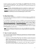
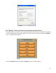
Specifications

17
Figure 5
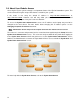
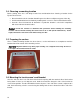
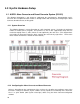
3.7 Terminations
Before terminating the communication and power cables, take a moment to get familiarized with the
connection points on the touch screen, shown in Figure 6.
Figure 6
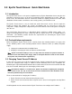
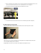
1. Start by crimping a connector onto the Ethernet cable. Performing this step first is very
important, since it won’t be able to set the touch screen aside once the power has been
connected.
Note: EyeOn recommends using the T568-B or T568-A standard. (Note that this wiring standard
must also be used at the switch or router.)
2. Prepare the 16-gauge/3-conductor power cable by stripping away 1.25” of the outer insulation.
3. Next, strip 1/4” inch of insulation from each wire.