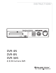
INSTRUCTIONS ' ' " ' PRESET REW SPOT FUNCTION AUTO FREEZE PTZ COPY SEARCH SLOW LIVE/PB FAST DIR PLAY/ PAUSE REC MENU STANDBY 1 2 3 HDD ! RX/TX REC PLAY 4 5 6 7 8 9 +10 0 ESC ALARM RESET STATUS D-ZOOM HOME MULTI PIP CAMERA / NUMBER INPUT DVR-4N DVR-8N DVR-16N 4/8/16 Camera DVR 6 ; FF ;
WARNING This symbol is intended to alert the user to the presence of unprotected “Dangerous voltage" within the product's enclosure that may be strong enough to cause a risk of electric shock. This symbol is intended to alert the user to the presence of important operating and maintenance (servicing) instructions in the literature accompanying the appliance. WARNING TO REDUCE THE RISK OF FIRE OR ELECTRIC SHOCK, DO NOT EXPOSE THIS APPLIANCE TO RAIN OR MOISTURE.
PRECAUTION All the safety and operating instructions must be read before the unit is operated. • Make sure to switch the power off before you install the DVR. • There is the danger of an electric shock if the DVR is opened by an unqualified service engineer or installer. • Avoid using the DVR outside of the reference temperature and humidity indicated in the specification. • Avoid exposing the DVR to violent movement or vibration.
CONTENTS CONTENTS CHAPTER 1 CHAPTER 2 CHAPTER 3 CHAPTER 4 CHAPTER 5 CHAPTER 6 CHAPTER 7 CHAPTER 8 CHAPTER 9 FEATURES .............................................................................. 4 PACKING DETAIL .................................................................... 6 LOCATION AND CONTROL ..................................................... 7 3.1 FRONT PANEL CONTROLS ............................................ 7 3.2 REAR PANEL CONNECTORS .........................................
FEATURES Chapter 1 Features Operation Playback, recording, backup and transmission simultaneously Real time single or multi-screen display Pan & Tilt, 2X/4X digital zoom and PIP display Easy operation by Jog shuttle, IR remote controller, external keypad controller and USB 2.
FEATURES Audio 4 channels audio recording in real time Copy USB 2.0 external HDD USB 2.
PACKING DETAIL Chapter 2 Packing Detail F(-) F(+) AUTO FREEZE (AF) (PRESET) COPY SEARCH REW SPOT FUNCTION PTZ SLOW LIVE/PB FAST DIR PLAY/ PAUSE REC Z(-) FF Z(+) MENU STANDBY 2 3 4 5 6 7 8 9 +10 0 1 HDD @ RX/TX REC PLAY ALARM RESET ESC D-ZOOM STATUS (HOME) MULTI PIP CAMERA / NUMBER INPUT 1. DVR 2. Network Viewer Program CD 5. R-HDD Rack Key (option) 3. User’s Manual 6. Power Cord CONTENTS 1. DVR 2. Network Viewer Program CD 3. User’s Manual 4.
LOCATION AND CONTROL Chapter 3 Location and Control 3.
LOCATION AND CONTROL 3.
INSTALLATION Chapter 4 Installation 4.
INSTALLATION 4.2 INDIVIDUAL CONNECTION 4.2.1 Camera * Connect a female BNC connector of each camera to a male BNC connector, “CAMERA IN” port. * Connect the looping BNC output to other inputs as required.
INSTALLATION 4.2.2 Audio (*Refer to the specification) Audio Input - AUDIO IN : Connect the RCA Line Jack of the relevant equipment (for example, a camera with a built-in microphone) to the AUDIO IN port. Audio Output - AUDIO OUT : Connect the RCA Line output to a monitor with a built-in speaker. NOTE This DVR can be connected only with a line audio and not support a microphone for audio input and output. To record audio should be enable in the AUDIO setup at the MENU setup.
INSTALLATION 4.2.3 Monitor - Connect the female BNC for monitor output. - Connect the male Y/C cable socket for S-VIDEO monitor output. 4.2.4 Power CAUTION RISK OF ELECTRIC SHOCK DO NOT OPEN WARNING: TO REDUCE THE RISK OF FIRE OR ELECTRIC SHOCK AC110~240V 50/ 60Hz - Auto-detect the correct voltage of power (110~240 VAC) - Connect the power cord.
INSTALLATION 4.2.5 USB 2.0 ports 1 Three USB ports are provided to connect a USB memory stick, external storage devices and ○ CD-RW/DVD-RW for video clip copying. One USB port is on the front panel and the other two are on the rear panel. 2 A USB mouse can be connected to one of the ports. You can use the mouse to navigate ○ through the screens and menus much like you would on a computer. Installation Process Connect the desired device to the DVR, as shown above.
OPERATION Chapter 5 Operation 5.1 FACTORY DEFAULT MENU Setup> QUICK SETUP> QUICK SETUP…………………………..………OFF IMAGE SIZE………………………………………720x240 RECORD FRAME…………………………………60 EVENT……………………….…..…………...........ALL PRE RECORD TIME……….……………………..5 sec POST RECORD TIME………………………..…..10 sec IMAGE QUALITY.. ………………………………FINE AUDIO RECORD ………………………………….OFF REMOTE CONTROL ID.…………….………..… ..ALL SCREEN> POSITION HORIZONTAL POSITION………………….0 VERTICAL POSITION.……………………..
OPERATION ADD SPOT MULTI……………………………....OFF RECORD> RECORD SETUP RECORD PROGRAM..………………….……......6 RECORD PROGRAM (Refer to page 52) IMAGE QUALITY RECORD QUALITY……………………….…….....FINE AUDIO RECORD AUDIO 1………………..…………………….…...... OFF AUDIO 2………………..…………………….…...... OFF AUDIO 3………………..…………………….…...... OFF AUDIO 4……………..……………………….…...... OFF REPEAT RECORD REPEAT RECORD..………………………………..ON REPEAT RECORD ALARM.…………………..…..5% PLAY MODE.…………………………………….……........FRAME BACKUP MODE..……………………………….……........
OPERATION REC/PLAY CHECK…..………………….……………....…OFF VIDEO STANDARD…………….…………………………..AUTO LANGUAGE……………….………..………………….…….ENGLISH REMOTE CONTROL ID.…………….………..…………….ALL KEY ECHO…..………………….……………………………ON DVR INITIALIZE.………………….………..………………..NO FIRMWARE UPGRADE………………….…………………NO LINK> NETWORK DHCP……..……………………………………………OFF RS-232 BAUD RATE..………………….……………………..115200 DATA BIT……..……………………………………….8 PARITY BIT….……..…………………………………NONE STOP BIT……..……………………………………….1 RS-422/485 SYSTEM ID……..…………………………………….1 OUTPUT MODE.
OPERATION 5.2 FRONT PANEL CONTROLS 5.2.1 POWER ON/ OFF SWITCH(located in rear panel) After the connection of power cord and other devices(HDDS) with this DVR, turn the power on. a. The video signal system (NTSC or PAL) is automatically detected. b. Power Failure Recovery This DVR automatically reverts back to programmed record parameters upon power restoration. c. If the power key is protected by password, the power on/off cannot be executed before input the correct password.
OPERATION Use the +10 Button when you select two digit camera numbers. EX) Camera Number 12 = Press the +10 Button, and then press the No. 2 Button. CAMERA/NUMBER INPUT buttons are used to input the password in the password lock function. 5.2.2.2 Auto Sequence Display example for 16CH - Press the AUTO button, each screen display will be automatically switching according to the AUTO SEQUENCE setup.
OPERATION 5.2.3 RECORD Press the REC button and the following message will be displayed as below; MANUAL MODE Press the REC button to begin recording. To stop recording, press the REC button again. The screen will be turned into real time display mode. SCHEDULE MODE When Schedule mode is selected, the recording will be automatically executed according to the recording schedule. (Please refer to the RECORD PROGRAM in the RECORD setup, page 47.
- OPERATION 5.2.4.1 CALENDAR SEARCH At the SEARCH menu; ① Move the cursor to CALENDAR SEARCH using © or ª button. ② Press the ENTER button and CALENDAR SEARCH screen appears. ③ Select the desired HDD ID using the (-) or (+) button. ④ Move the cursor to CHANNEL using the © or ª button and select the desired channel using the (-) or (+) button. ⑤ Move the cursor to the desired position using the © , ª , § , ¨ buttons, and then select the desired date.
- OPERATION 5.2.4.2 SEARCH & COPY At the SEARCH menu; ① Move the cursor to SEARCH & COPY using © or ª button. ② Press the ENTER button and SEARCH & COPY screen appears. ③ Select the desired HDD ID using the (-) or (+) button. ④ Move the cursor to CHANNEL using the © or ª button and select the desired channel using the (-) or (+) button.
- OPERATION 5.2.4.4 EVENT SEARCH At the SEARCH menu; ① Move the cursor to EVENT SEARCH using © or ª button. ② Press the ENTER button and the EVENT SEARCH menu screen appears. ③ Select the desired HDD ID using the (-) or (+) button. ④ Move the cursor to CHANNEL using the © or ª button and select the desired channel using the (-) or (+) button. ⑤ Move the cursor to EVENT using the © or ª button and select the event type to search using the (-) or (+) button.
- OPERATION ③ Select the desired HDD ID using the (-) or (+) button. ④ Move the cursor to the desired position of SEARCH TIME using the © , ª , § , ¨ buttons, and then set up the desired time using the(-), (+) buttons. (Or turn the wheel scroll of mouse to search the block list.) ⑤ Press the ENTER or turn the wheel scroll of mouse, and the list searched appears.
- OPERATION ③ Press the ENTER button, and the list searched appears. ④ When the list appears on the screen, select the desired list using © or ª buttons or wheel scroll of mouse ⑤ Press the ENTER button for the playback. ① Press the “PB/PAUSE” button to playback. ② Find the desired image using shuttle ring. ③ Press the “PB/PAUSE” button to see the still picture of the desired image. ④ Press the “PTZ” button to add the BOOKMARK list. 5.2.4.
- OPERATION 5.2.5 SEARCH BUTTON INFORMATION 1 ○ 2 ○ 3 ○ 4 ○ 5.1.5.1 SLOW ( ) Press this button to make the speed level which is slower than normal speed (X1) and displayed it at the upper left side of screen as below; (If you press this button again, the playback speed will be changed in the order of the below seven speed level) i. 1/2 - 2 times slower than normal playback speed ii. 1/4 - 4 times slower than normal playback speed iii. 1/8 - 8 times slower than normal playback speed iv.
- OPERATION NOTE Press DIR button to make a reversed playback from the end of recorded or played images during the real time display mode (Instant Playback). 5.2.6 JOG SHUTTLE INFORMATION SHUTTLE RING JOG DIAL 5.2.6.1 Normal Playback Mode ① Turn the SHUTTLE ring to the desired playback direction and speed level according to the above drawing during the playback. ② The DVR will go back to pause mode when the SHUTTLE ring is returned to the center position. 5.2.6.
- OPERATION 5.2.7 DIGITAL ZOOM CH1 ① ② ③ ④ ⑤ Press the desired camera number button you wish to display on the monitor. Press the D-ZOOM button. The indication screen appears on the main screen. Turn wheel scroll of mouse or press the © , ª , § , ¨ buttons to select the desired location. Press the ENTER button to change the zoom x2 ~ x4. Press the ESC button to exit this screen. 5.2.
- OPERATION ** Please refer to 6.2.7 SPOT of SCREEN 5.2.10 COPY Press the COPY button to copy the recorded images into other media and the COPY MENU screen appears. 5.2.10.1 COPY 5.2.10.1-1 COPY TO EXTERNAL HDD (USB) At the COPY menu, ① Move the cursor to COPY using the © or ª buttons. ② Press the ENTER button and the following screen appears. ③ Select the desired MEDIA(USB port 3 select the correct USB position for HDD) (-), (+) buttons or wheel scroll of mouse.
- OPERATION ④ Move the cursor to HDD ID using the © or ª buttons and select the desired HDD to copy among HDD IDs using the (-), (+) buttons or wheel scroll of mouse. ⑤ Move the cursor to the desired position of COPY START TIME/ COPY END TIME using the © , ª , § , ¨ buttons and press the (-) or (+) button to set up the time to set up the COPY START TIME and COPY END TIME.
OPERATION ** Scroll bar: - Turn the shuttle ring to the right to move the cursor of COPY END TIME or to the left to move the cursor of COPY START TIME and the cursor will be yellow. And then turn the wheel scroll of mouse to move the cursor to the desired time. - It can operate with just Mouse click. ⑥ Press the ENTER button to copy. When the copy is in process, the copying status(ex. “COPY 30%”) will be displayed on the right side of the monitor.
OPERATION When the copy is in process, the copying status(ex. “COPY 30%”) will be displayed on the right side of the monitor. NOTE - CD-RW or DVD-RW is option and this DVR need the interface board to install a built-in CD-RW or DVD-RW. - If you want a built-in CD-RW or DVD-RW, must purchase it from a authorized dealer. - You can search and playback the copied images in CD or DVD with DVR itself as well as PC. (Please refer to 5.2.4.6 FILE SEARCH, page 23.
OPERATION 5.2.10.3 MEDIA FORMAT At the COPY menu, ① Move the cursor to MEDIA FORMAT using the © or ª buttons. ② Press the ENTER button and the following screen appears. ③ Select formatting media using the (-), (+) button. ④ Move the cursor to MEDIA FORMAT and then press the “ENTER” button. ⑤ The message, “FORMATTING” will be displayed while formatting. NOTE If you don’t connect any media device, you can see the message, “Fail”. 5.2.
OPERATION ② ③ ④ ⑤ ⑥ Press the “PTZ” button to control pan, tilt and zoom functions of PTZ camera. Use the § , ¨ button to pan left and right and the © or ª button to tilt up and down. Turn the SHUTTLE ring to zoom in and out. Use the (-) or (+) button to focus. Or press the (AF) button for auto focusing. Press the PTZ button again to exit the PTZ mode. ** Please refer to 6.6.4 PTZ setup of LINK menu, page 74. 5.2.12.2 PTZ PRESETTING ① Press the “PTZ” button to enter PTZ mode.
OPERATION 5.2.13 FUNCTION BUTTON
- OPERATION 5.
- MENU SETUP 5.4 MOUSE CONTROL 1 ○ 2 ○ 3 ○ 1 ○ 3 ○ 3 ○ 2 ○ 1 ○ Status display Menu display Exit Value change Select Double-click Doubl e-click of the left button One-click of the right button Double-click of the right button Turning the wheel scroll Double-click on the item or icon * You can click the below keys on the MENU screen with a mouse. mouse.
- MENU SETUP Chapter 6 MENU Setup ENTRANCE OF THE MENU SETUP Press the MENU button for the desired DVR setting. You can use the mouse instead of buttons on the front panel of DVR. Simply click the desired icon or item in case of using the mouse. 6.1 QUICK SETUP Press the MENU button and the QUICK SETUP menu appears as the following picture. ** This menu is simply used when user want to change just a few important settings.
- MENU SETUP 6.1.1 QUICK SETUP Select “ON” or “OFF” using the (-), (+) buttons or wheel scroll of mouse to use the QUICK SETUP setting. NOTE : If you select “ON”, RECORD MENU will be disregarded. 6.1.2 IMAGE SIZE Select the desired IMAGE SIZE for recording using the (-), (+) buttons or wheel scroll of mouse. 6.1.3 RECORD FRAME Select the desired frame rate for normal recording using the (-), (+) buttons or wheel scroll of mouse. All event channels will be recorded by the setting RECORD FRAME/16.
- MENU SETUP 6.1.8 REMOTE CONTROL ID At the SYSTEM menu, ① Move the cursor to the REMOTE CONTROL ID using the © or ª buttons. ② Set the REMOTE CONTROL ID using the (-), (+) buttons or wheel scroll of mouse. If you are operating more than one DVR in the same place and wish to use the remote controller, the remote controller ID setup is required. Otherwise, do not change the default set value and “ON” should be selected.
- MENU SETUP ② Change the value of the HORIZONTAL POSITION using the (-), (+) buttons or wheel scroll of mouse to adjust the horizontal position of the screen. * The value is from -4 to +4 and the default is “0”. ③ Change the value of the VERTICAL POSITION using the (-), (+) buttons or wheel scroll of mouse to adjust the vertical position of the screen. * The value is from -4 to +4 and the default is “0”. ④ To exit this POSITION menu, press the ESC button. 6.2.
- MENU SETUP 6.2.3 DISPLAY At the SCREEN menu, ① Move the cursor to the DISPLAY using © or ª buttons. ② Press the ENTER button when the cursor is on the DISPLAY and the following items appear. ③ To exit this DISPLAY menu, press the ESC button. 6.2.3.1 HDD FREE SPACE At the DISPLAY menu, ① Move the cursor using the © or ª buttons to select the HDD FREE SPACE. ② Use the (-), (+) buttons or wheel scroll of mouse to choose “ON” or “OFF”. * The default is “ON”.
- MENU SETUP ON: The date and time will be displayed on the screen. 6.2.3.5 DATE&TIME MODE At the DISPLAY menu, ① Move the cursor using the © or ª buttons to select the DATE&TIME MODE. ② Use the (-), (+) buttons or wheel scroll of mouse to choose “NUMBER” or “INITIAL”. * The default is “NUMBER”. NUMBER: All date and time will be displayed in numbers. Ex. 2005/01/01 00:00:00 INITIAL : the month section will be displayed in character. Ex. JAN. 01 2005 00:00:00 6.2.3.
- MENU SETUP 6.2.4 TITLE At the SCREEN menu, ① Move the cursor to the TITLE using © or ª buttons. ② Press the ENTER button when the cursor is on the TITLE and the following 2 pages screen appears. ③ Use the § , ¨ buttons to see the next page. ④ Press the ENTER button after selecting desired channel using the © or ª buttons and the following screen appears. ⑤ Select the character using the © , ª , § , ¨ buttons and then press the ENTER button. ⑥ To exit this CHARACTER TABLE screen, press the ESC button.
- MENU SETUP At the SCREEN menu, ① Move the cursor to the MULTI SCREEN using © or ª buttons. ② Select the character using the © , ª , § , ¨ buttons and then press the ENTER button. ③ Press the ENTER button when the cursor is on the MULTI SCREEN and the following screen appears. ④ To exit this MULTI SCREEN menu, press the ESC button. 6.2.5.1 LIVE 4E / LIVE 7/ LIVE 9B/ LIVE 10/ LIVE 13 ① Press the ENTER button after selecting “LIVE 4E、7、9B、10、13” using the © or ª buttons.
- MENU SETUP [LIVE 13] ② Set the desired number of camera in each channel screen using the (-), (+) buttons or wheel scroll of mouse. ③ Use the © , ª , § , ¨ buttons to set the other channel screen. ④ To exit this screen, press the ESC button. Note: In the each of LIVE SPLIT, same camera numbers should not be selected. 8CH have a 4、6、7 split screen using this menu. 4CH version don’t have this option. 6.2.6 COVERT At the SCREEN menu, ① Move the cursor to the COVERT using the © or ª buttons.
- MENU SETUP 6.2.7 SPOT At the SCREEN menu, ① Move the cursor to the SPOT using © or ª buttons. ② Press the ENTER button when the cursor is on the SPOT and the following screen appears. ③ To exit this SPOT menu, press the ESC button. 6.2.7.1 SPOT MODE ① Use the (-), (+) buttons or wheel scroll of mouse to select the SPOT MODE. - MANUAL: Manually select the channel of spot monitor. - EVENT: Event channel will be displayed automatically on spot monitor.
- MENU SETUP 6.3.1 RECORD SETUP At the RECORD menu, ① Move the cursor to the RECORD SETUP using © or ª buttons. ② Press the ENTER button when the cursor is on the RECORD SETUP and the following screen appears. ③ Move the cursor to choose the desired time using the © , ª , § , ¨ buttons. ④ Select the desired program among PROGRAM 0~9 and POWER OFF using the (-), (+) buttons or wheel scroll of mouse.
- MENU SETUP ② Press the ENTER button when the cursor is on the RECORD PROGRAM and the following screen appears. ③ Use the © , ª , § , ¨ buttons to move the cursor to the desired item. ④ Select the desired RECORD TYPE using the (-), (+) buttons or wheel scroll of mouse. - SINGLE : Only one event channel will be recorded by setting event recording frame rate and the other channels will be recorded by rest event recording fps/N(channel number) when an event happened.
- MENU SETUP < Result table of total frame rate > Record Type Image Size Normal Record Single 360 x 240 720 x 240 720 x 480 360 x 240 720 x 240 720 x 480 Normal Frame Normal Frame Normal Frame Normal Frame Normal Frame Normal Frame Complex Event Record Event Channel Other Channel ES_Frame RS_Frame ES_Frame RS_Frame ES_Frame RS_Frame EC_Frame EC_Frame EC_Frame EC_Frame EC_Frame EC_Frame Unit CIF/1 SEC CIF/1 SEC CIF/1 SEC CIF/1 SEC CIF/1 SEC CIF/1 SEC - ES_Frame : Event single frame rate.
MENU SETUP < PROGRAM DEFAULT> These are 10 kinds of program and you can change the program setting.
MENU SETUP NOTE RECORD TIME: A period how long you can record in free space of installed HDD(s) by setting of Max. frame rate. TOTAL TIME: A period how long you can record in total installed HDD(s) by setting of Max. frame rate. ** The better the image quality is, the bigger the file size is and the worse the image quality, the smaller the file size is. 6.3.4 AUDIO RECORD At the RECORD menu, ① Move the cursor to the AUDIO RECORD using the © , ª buttons.
MENU SETUP ③ Use the (-), (+) buttons or wheel scroll of mouse to set “ON” or “OFF”. ④ It is possible to set a point of time to work the REPEAT RECORD ALARM. Move the cursor to ”REPEAT RECORD ALARM” using © , ª buttons and then select the desired value using (-), (+) buttons or wheel scroll of mouse. The value is from 5% to 10%. ⑤ To exit this REPEAT RECORD menu, press the ESC button. ON: The recorded data will be overwritten when it is a point of time to work the REPEAT RECORD.
MENU SETUP ③ Set up “ON” or “OFF” of HOLIDAY RECORD using the (-), (+) buttons or wheel scroll of mouse. ④ Move the cursor using © , ª buttons and set up the value using the (-), (+) buttons or wheel scroll of mouse. ⑤ To exit this HOLIDAY menu, press the ESC button. 6.4 EVENT To set up the EVENT menu, ① Move the cursor to the EVENT icon using the § , ¨ in the MENU screen. ② Press the ENTER button when the cursor is on the EVENT icon and the following items appear. 6.4.
MENU SETUP 6.4.1.1 CHANNEL At the MOTION DETECTION menu, ① Move the cursor to CHANNEL using © , ª buttons. ② Select the desired channel using the (-), (+) buttons or wheel scroll of mouse. ③ Under Event option, move the cursor to the EVENT MESSAGE using © , ª buttons. ④ Select “ON” or “OFF” using the (-), (+) buttons or wheel scroll of mouse. 6.4.1.2 SENSITIVITY At the MOTION DETECTION menu, ① Move the cursor to SENSITIVITY SENSITIVITY using © , ª buttons.
MENU SETUP 6.4.4 EVENT MESSAGE At the EVENT menu, ① Move the cursor to the EVENT MESSAGE using © , ª buttons. ② Select “ON” or “OFF” using the (-), (+) buttons or wheel scroll of mouse ON: The warning message will be displayed when the event occurs. 6.4.5 EVENT MESSAGE RESET At the EVENT menu, ① Move the cursor to the EVENT MESSAGE RESET using © , ª buttons. ② Set the time to reset the event message from 1SEC to 30SEC using the (-), (+) buttons or wheel scroll of mouse. 6.4.
MENU SETUP 6.4.8 RELAY OUTPUT At the EVENT menu, ① Move the cursor to the “RELAY OUTPUT” using the © , ª buttons. ② Press the ENTER button when the cursor is on the “RELAY OUTPUT” and the following screen appears. ③ Move the cursor using the © , ª , § , ¨ buttons and set up the value using the (-), (+) buttons or wheel scroll of mouse. ④ Press the § button to see the next page. ⑤ To exit this screen, press the “ESC” button. NOTE - It is possible to set the RELAY OUTPUT of each channel in the type of event.
- MENU SETUP 6.5 SYSTEM To set up the SYSTEM menu, ① Move the cursor to the SYSTEM icon using the § , ¨ in the MENU screen. ② Press the ENTER button when the cursor is on the SYSTEM icon and the following items appear. 6.5.1 HDD At the SYSTEM menu, ① Move the cursor to the HDD using the © , ª buttons. ② Press the ENTER button when the cursor is on the HDD and the following screen appears. ③ To exit this HDD menu, press the ESC button. 6.5.1.
MENU SETUP ③ Use the © , ª , § , ¨ buttons to move the cursor and use the (-), (+) buttons or wheel scroll of mouse to change the value. HDD MODE - REC: Normal and Event recording - BACKUP: Only for backup 6.5.1.2 REC HDD INITIALIZE At the HDD menu, ① Move the cursor to REC HDD INITIALIZE using the © , ª buttons. ② Press the ENTER button when the cursor is on the REC HDD INITIALIZE and the following screen appears. ③ If you want to initialize, move the cursor to “YES” and then press the “ENTER” button.
- MENU SETUP ③ If you want to initialize, move the cursor to “YES” and then press the ENTER button. If not, move the cursor to “NO” and then press the ENTER button. ④ To exit this screen, press the ESC button. ⑤ To exit this HDD menu, press the “ESC” button again. 6.5.2 CLOCK At the SYSTEM menu, ① Move the cursor to the CLOCK using the © , ª buttons. ② Press the ENTER button when the cursor is on the CLOCK and the following screen appears. 6.5.2.
- MENU SETUP ③ Use the © , ª , § , ¨ buttons to move the cursor to the desired position of date or time. ④ Use the (-), (+) buttons or wheel scroll of mouse to modify the current date and time. - DATE: YYYY/MM/DD YEAR/MONTH/DAY - TIME : HH:MM:SS HOUR:MINUTE:SECOND ⑤ To exit this DATE & TIME screen, press the ESC button. 6.5.2.2 TIME ADJUST At the CLOCK menu, ① Move the cursor to the TIME ADJUST using the , buttons.
- MENU SETUP POWER OFF CHECK At the SYSTEM menu, ① Move the cursor to the PASSWORD using the © , ª buttons. ② Press the ENTER button when the cursor is on the PASSWORD and the following screen appears. ③ To exit this PASSWORD menu, press the ESC button. 6.5.3.1 MASTER PASSWORD At the PASSWORD menu, ① Move the cursor to the MASTER PASSWORD using the © , ª buttons. ② Press the ENTER button when the cursor is on the MASTER PASSWORD and the following screen appears.
- MENU SETUP ⑤ And you have to insert the same numbers again to verify the password after entering the NEW PASSWORD. ⑥ To exit this MASTER PASSWORD menu, press the ESC button. 6.5.3.2 SUPERVISOR PASSWORD At the PASSWORD menu, ① Move the cursor to the SUPERVISOR PASSWORD using the © , ª buttons. ② Press the ENTER button when the cursor is on the SUPERVISOR PASSWORD and the following screen appears.
- MENU SETUP 6.5.3.5 REC/PLAY CHECK At the PASSWORD menu, ① Move the cursor to the REC/PLAY CHECK using the © , ª buttons. ② Select “ON” or “OFF” to set up the REC/PLAY CHECK using the (-), (+) buttons or wheel scroll of mouse. If REC/PLAY CHECK is “ON”, the password will be required when you start/stop to record or playback. The default is “OFF”. 6.5.4 VIDEO STANDARD At the SYSTEM menu, ① Move the cursor to the VIDEO STANDARD using the © , ª buttons.
- MENU SETUP 6.5.8 DVR INITIALIZE At the SYSTEM menu, ① Move the cursor to the DVR INITIALIZE using the © , ª buttons. ② Press the ENTER button when the cursor is on the DVR INITIALIZE and the following screen appears. ③ If you want to initialize, move the cursor to “YES” and then press the ENTER button. If not, move the cursor to “NO” and then press the ENTER button. Use the © , ª buttons to move the cursor. ④ To exit this DVR INITIALIZE screen, press the ESC button. 6.5.
- MENU SETUP 6.6 LINK To set up the LINK menu, ① Move the cursor to the LINK icon using the § , ¨ in the MENU screen. ② Press the ENTER button when the cursor is on the LINK icon and the following items appear. 6.6.1 NETWORK At the LINK menu, ① Move the cursor to the NETWORK using the © , ª buttons. ② Press the ENTER button when the cursor is on the NETWORK and the following screen appears. ③ To exit this NETWORK menu, press the ESC button. 6.6.1.
- MENU SETUP 6.6.1.2 IP ADDRESS At the NETWORK menu, ① Move the cursor to the IP ADDRESS using the © , ª buttons. ② Select the desired position using the § , ¨ buttons and set the data value using the (-), (+) buttons or wheel scroll of mouse. 6.6.1.3 SUBNET MASK At the NETWORK menu, ① Move the cursor to the SUBNET MASK using the © , ª buttons. ② Select the desired position using the § , ¨ buttons and set the data value using the (-), (+) buttons or wheel scroll of mouse. 6.6.1.
- MENU SETUP 67
- MENU SETUP 6.6.2 RS-232 At the LINK menu, ① Move the cursor to the RS-232 using the © , ª buttons. ② Press the ENTER button when the cursor is on the RS-232 and the following screen appears. ③ Use the © , ª buttons to choose the item and use the (-), (+) buttons or wheel scroll of mouse to set the data value. ④ To exit this RS-232 menu, press the ESC button. 6.6.3 RS-422/485 At the LINK menu, ① Move the cursor to the RS-422/485 using the © , ª buttons.
- MENU SETUP 6.6.4 PTZ At the LINK menu, ① Move the cursor to the PTZ using © , ª buttons. ② Press the ENTER button when the cursor is on the PTZ and the following 2 pages screen appears. ③ Select the desired channel using © , ª buttons. ④ Use the (-), (+) buttons or wheel scroll of mouse to select the right model of installed PTZ camera. ⑤ Press the ¨ button to set up a ID of the PTZ camera. ⑥ Use the (-), (+) buttons or wheel scroll of mouse to select the desired ID.
- MENU SETUP 6.6.5.1 SEND E-MAIL At the E-MAIL menu, Move the cursor to the SEND E-MAIL using the © , ª buttons and select “ON” using the (-), (+) buttons to send a e-mail when an event happened. MENU 6.6.5.2 SMTP SERVER At the E-MAIL menu, ① Move the cursor to the SMTP SERVER using the © , ª buttons to input the e-mail sever address to be used by DVR. ② Press the ENTER button and the following screen appears. ③ Select the character using the © , ª , § , ¨ buttons and then press the ENTER button.
- MENU SETUP 6.6.5.4 PASSWORD At the E-MAIL menu, ① Move the cursor to the PASSWORD using the © , ª buttons to input the account password to be used by DVR. ② Press the ENTER button and the following screen appears. ③ Select the character using the © , ª , § , ¨ buttons and then press the ENTER button. ④ To exit this CHARACTER TABLE screen, press the ESC button. 6.6.5.
- MENU SETUP 6.7 SEARCH To set up the SEARCH menu, ① Move the cursor to the SEARCH icon using the § , ¨ in the MENU screen. ② Press the ENTER button when the cursor is on the SEARCH icon and the following items appear. ** Please, refer to Search & Playback of Chapter 5 Operation. 6.8 COPY To set up the COPY menu, ① Move the cursor to the COPY icon using the § , ¨ in the MENU screen. ② Press the ENTER button when the cursor is on the COPY icon and the following items appear.
- MENU SETUP 6.9 EXIT At the MENU screen, ① Move the cursor to the EXIT icon using the § , ¨ buttons. ② Press the ENTER button when the cursor is on the EXIT icon and the following items appear. ③ Move the cursor to the desired item using the © , ª buttons and press the ENTER button. - SAVE ONLY : Select this item if you want only to save the changed setup. - SAVE AND EXIT : Select this item if you want to save the changed setup and exit this screen.
EXTERNAL TERMINAL INFORMATION Chapter 7 External Terminal Information 7.1 RS-422/485 This port can be used to connect the external controller. 7.2 T.ADJ This function is not supported.
EXTERNAL TERMINAL INFORMATION 7.3 RELAY OUT For controlling alarm output by relay. 13 25 1 RS-422/485 / T-ADJ / RELAY OUT 14 NO. RS-422/485 / T-ADJ / RELAY OUT 9 NC 1 CM 1 ALARM 10 11 NO 1 NC 2 12 CM 2 V - LOSS 13 14 NO 2 15 NC 3 MOTION CM 3 16 DETECTION NO 3 17 18 NC 4 POWER / CM 4 19 HDD ERROR NO 4 20 7.
EXTERNAL TERMINAL INFORMATION 7.5 VGA This DVR is compatible with TFT LCD monitor in PAL mode. This DVR supports 1024 x 768 resolution & 70Hz refreshed rate in NTSC/PAL mode. VGA No DESCRIPTION 1 RED(Red Video [75ohm, 0.7Vp-p] ) 2 GREEN(Green Video [75ohm, 0.7Vp-p] ) 3 BLUE(Blue Video [75ohm, 0.7Vp-p] ) 4~12 Reserved 13 HSYNC or CSYNC(Horizontal or Composite Sync.) 14 VSYNC(Vertical Sync.) 15 Reserved 7.6 SERIAL This DVR is compatible with TFT LCD monitor in PAL mode.
- EXTERNAL TERMINAL INFORMATION 7.7 Ethernet / USB For both 10Base-T and 100 Base-TX. No DESCRIPTION 1 N/C (Not Connected) 2 N/C (Not Connected) 3 RX-(Receive Data-) 4 N/C (Not Connected) 5 N/C (Not Connected) 6 RX+(Receive Data+) 7 TX-(Transmit Data-) 8 TX+(Transmit Data+) No DESCRIPTION 1 VCC ETHERNET USB2 USB1 2 USB DATA - 3 USB DATA + 4 GND Note: Definition (under Menu option): USB1 = USB_REAR1 USB2 = USB_REAR2 7.
SPECIFICATIONS Chapter 8 Specifications 1. VIDEO Input Level 1.0 Vp-p±10% Composite, 75Ω Balanced Video Standard NTSC(525 lines)/ PAL(625 lines)/ AUTO Display Speed Display Resolution Monitor Output NTSC 480/ 240/120 (16/ 8/ 4CH Real Time) PAL 400/ 200/100 fps (16/ 8/ 4CH Real Time) NTSC 720(H) X 480(V) PAL 720(H) X 576(V) Main 1.0Vp-p Composite, 75Ω Balanced (YC Output) Spot 1.0Vp-p Composite, 75Ω Balanced Analogue non-interlaced RGB.
- SPECIFICATION Remote Serial PTZ control Alarm Input Alarm Output Ethernet Reserved External control (RS-232C) / For debugging : 9 pins male DSUB RS-485 16/ 8/4CH 4 Relay output : 3 pins terminal block (Normal-Open, Normal-Close, Common) x 4 RJ45 connector, 10/100 Mbps 7. ELECTRICAL Power Source 110~220VAC (50~60Hz) : Auto-detection Power Consumption App. 70W(Including 1 HDD) 8.
- SPECIFICATION < Recording Speed Table > Model Recording Speed NTSC PAL 360 x 240 720 x 240 720 x 480 360 x 288 720 x 288 720 x 576 Compression Method 16-CH DVR 120 60 30 100 50 25 MPEG4 8-CH DVR 120 60 30 100 50 25 MPEG4 Unit : fps 4-CH DVR 120 60 30 100 50 25 MPEG4 < Recording Time Table > 1. RECORDING CONDITIONS Based on 120GB of storage with the installation of 1 camera. This DVR can support up to 22TB with external HDD storage devices.. 2.
HDD DD INSTALLATION PROCESS 8.1 INSTALL the INTERNAL HARD DISK DRIVE(s). Note: (Set the master or slave of HDD before fixing the HDD(s) into DVR. Refer to HDD jumper settin g information.) Note: Set up no. 1 and 3 by master and no. 2 and 4 by slave. PCI SLOT Description Jumper Setting A For Removable HDD (Optional) Master B For Fixed HDD (1 and 2) No.1 for Master and No.2 for Slave C For Fixed HDD (3 and 4) No.3 for Master and No.
- NETWORK VIEWER INSTALLATION Chapter 9 Network Viewer 9.1 INSTALLATION of NETWORK VIEWER SOFTWARE 9.1.1 System requirement - Pentium III or above recommended - O/S : Microsoft Windows 2000 / XP - 128MB RAM or above recommended - Super VGA 16M or above recommended - 10/100 base T network card for LAN operation 9.1.2 Network Environment Minimum Recommended (16 Frames/Sec) Client PC DVR More than 1Mbps More than 0.
- NETWORK VIEWER INSTALLATION 9.2.1 ADD a NEW SITE INFORMATION 1 Click the “Select a DVR” button to display the DVR List on the screen. ○ 2 Fill out Type, DVR Name, IP address and Password to add the desired units into the DVR ○ information box, and then click on the “Add” button to save the information. 9.2.2 CHANGE the SITE INFORMATION 1 In case of any changes, type new information into the box after selecting the desired DVR on the ○ list. 2 Click the “Change” button to save the changes. ○ 9.2.
- NETWORK VIEWER INSTALLATION 9.3 DVR SEARCH This menu allows you to detect all the units on the local network. Search DVR 1 Click “Search DVR” button to display the “Search” menu window. ○ 2 Click the “Search” button, and then all the units on the local network will be detected and listed ○ on the screen. 3 Click the desired unit, and then click the “Add to list” button to add the unit into the “DVR list”. ○ 9.
NETWORK VIEWER INSTALLATION 9.5 FILE SEARCH At the above main menu controller, 1 Click the “File Search” button and the “File list” window will appear on the PC screen. ○ 2 If you want to search images saved in CD-RW, DVD-RW or PC, insert the CD or DVD into your ○ PC and click the “File Search” button and the File Search window will appear. 3 Click the “Folder Select” button and then select the desired folder and then click the “OK” button. ○ 4 Select the desired list and then click the “Play” button.
- NETWORK VIEWER INSTALLATION * 1 site windows * 2 ~ 4 site windows *5 ~ 9 site windows *10~16 site windows NOTE - You can connect up to 16 DVRs with your PC simultaneously. (16 users x 16 units: Master connection is only one.) - With the windows arranged in a grid, double-click the desired to make it the full screen 9.7 OPTION Insert the CD into the CD-ROM drive, and then please double-click the icon of Dvrviewer and the following main menu controller will appear on the PC screen.
NETWORK VIEWER INSTALLATION 9.8 CONTROL 9.8.1 Screen Display Images can be viewed in a full or multi format on each screen. a. Full screen display - Click the desired channel button and the full screen of the channel will be displayed. . b. Multi-screen display 1 Click the “MULTI” button and the multi-screen will be displayed. ○ 2 Click the “MULTI” button again to view other multi-screen.
- NETWORK VIEWER INSTALLATION NOTE If you need some more information about the control keys, please refer to Chapter 5 Operation. 9.8.3 PTZ This menu allows you to control the PTZ camera through the network. 1 Click the “PTZ” button to display the following PTZ controller. ○ 2 Click the ○ 3 Click the ○ and and button to tilt up or down. button to pan left or right. 4 Click the “ZOOM(- or +)” button to zoom in or out. ○ 5 Click the “FOCUS(- or +)” button to obtain the clearest picture.
NETWORK VIEWER INSTALLATION 1 Click the “SETUP” button on the control menu bar to display the DVR setup screen after ○ connecting the view screen. (It is possible only for master connection.) 2 Click the “Save to file” button to store the current setup values. ○ 3 Click the “Read from file” button to reload the stored setup values. ○ 4 Click the “Load from DVR” button to call the current setup values from connected DVR.
NETWORK VIEWER INSTALLATION After connecting the view screen, 1 Click the “PRINT” button on the control menu bar to print the desired image. ○ 2 And the preview window will be displayed as the above picture. ○ 3 Set up the desired option and then click the Print button of the preview window. ○ 9.8.7 COPY After connecting the view screen, 1 Click the “COPY” button on the control menu bar to copy the desired image. ○ 2 The Copy control window will appear.
NETWORK VIEWER INSTALLATION 2 You can hear the DVR sound from the speaker of your PC. ○ 9.8.10 TIME SEARCH You can search and playback the images by the time. After connecting the view screen, 1 Click the “TIME” button on the control menu bar to display the Time Search window. ○ 2 Select the desired HDD mode in the HDD dropdown list, and then click the “Search” button. ○ 3 When the recorded time information appears, select the desired “HDD” and the “Channel” and ○ set the “Search Time” for playback.
NETWORK VIEWER INSTALLATION 9.8.12 BLOCK SEARCH You can search and playback the images by the block. After connecting the view screen, 1 Click the “BLOCK” button on the control menu bar to display the Block Search window. ○ 2 Select the desired HDD mode and set the Search Time, and then click the “Search” button. ○ 3 When the list appears, select the desired list. ○ 4 Click the “Play” button of Block Search window to display the images on the screen. ○ 5 Click the “Next” button to search the next list.
NETWORK VIEWER INSTALLATION 9.9 KEY INFORMATION 9.9.1 PAUSE 1 Click this button to pause the images during the playback or live. ○ 9.9.2 PLAY (Reverse & Forward) 1 Use these buttons to playback images at normal speed in either direction. ○ 9.9.3 FAST (Reverse & Forward) 1 Use these buttons to playback images faster than normal speed in either direction. ○ 2 Multiple clicks of these buttons will increase the fast forward & the reverse speed. ○ 3 Various fast speed from x2 up to x128. ○ 9.9.
Channel Vision Technology will repair or replace any defect in material or workmanship which occurs during normal use of this product with new or rebuilt parts, free of charge in the USA, for two years from the date of original purchase. This is a no hassle warranty with no mail in warranty card needed. This warranty does not cover damages in shipment, failures caused by other products not supplied by Channel Vision Technology, or failures due to accident, misuse, abuse, or alteration of the equipment.