assembly guide Model Numbers: 11601514 11601559 11601578 11601514-c1 11601688 11601695-A1 Estimated time required for assembly: 1 Hour ELECTRIC (English) 42804382 • 9/16/10
A, B, C, Assembly: 2 ASSEMBLY GUIDE CAUTION: For your safety, before operating, Read Product Guide & Outdoor Cooking Guide provided with this grill. *SAFETY First…..Grill components may have sharp edges. Be careful when handling grill parts during assembly. We suggest that you wear a sturdy pair of leather gloves while handling the grill parts. BEFORE You begin assembly of your grill…. 1. Carefully remove all components from the carton. 2.
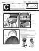
ASSEMBLY GUIDE Grill Parts Diagram F H D w A Q O V G X R B I B E L K C N P J S U U T Key Qty A 1 B 1 C 1 D 1 E 1 F 1 G 1 H 1 I 1 J 2 K 1 L 1 Description Grill Lid Lower Body Controller Element Assembly Wire Shelf Wind Shield Towel Bar Lid Handle Control Panel Wheel Rear Leg Set Front Leg Set M Key Qty M 1 N 2 O 1 P 2 Q 1 R 1 S 1 T 1 U 2 V 1 W 1 X 1 Description Grease Tray Hubcap Warming Rack Axle Heat Indicator Cooking Grate Cart Base Cart Bracket Leg Cap Heat Shield Inner Reflector Bez
ASSEMBLY GUIDE GRILL CART Assembly Part A1– Cart Base A2– Front Leg Set A3– Rear Leg Set A4– Wheels A5– Hubcap Qty 1 1 1 2 2 Fasteners . 1/4x20-1/2" screw (qty 4) Wheel Retaining Clip (qty 2) 3/8-16 Nut (qty 2) Step 1– Attach Front Leg Set (A2) to the Cart Base (A1) using 2 1/4-20 screws. Attach Rear Leg Set (A3) to the Cart Base (A1) in the same manner, using 2 1/4-20 screws. Axle Bolt (qty 2) After cart assembly, if your cart does not sit level, use these screws to adjust the cart.
ASSEMBLY GUIDE GRILL CART Assembly Fasteners Part A6– Cart Bracket A7– Wire Shelf A8– Leg End Cap Qty 1 1 2 . 1/4x20-2" screw (qty 4) 1/4-20 Nut (qty 4) #10x3/8" screw (qty 2) Step 3 - Carefully turn the Cart Assembly over and allow it to rest on the tops of the leg assemblies. Spread the leg assemblies apart just far enough to allow the insertion of the Wire Shelf (A7) into the 4 leg holes.
ASSEMBLY GUIDE GRILL BODY Assembly Fasteners Part Qty. B1– Lower Body 1 B2– Wind Shield 1 B3– Grill Lid 1 ASSEMBLY Step 1 - Attach the Lower Body Assembly (B1) to the Cart Assembly by aligning the studs on the bottom of the grill with the corresponding holes in the tops of the leg assemblies. Secure with 7 each 10-24 nuts. A Nut Driver (not supplied) will work nicely for this step.
ASSEMBLY GUIDE Part C1 – Cooking Grate C2 – Warming Rack C3 – Grease tray GRILL FINAL Assembly NOTE: The Cooking Grate may have sharp edges. Be very careful when handling the Cooking Grate. You should wear gloves when handling the Cooking Grate. Qty. 1 1 1 Step 1 - With the Grill Lid open, place the Cooking Grate (C1)into the Lower Body, allowing it to rest on the three brackets spaced around the Lower Body. Be sure the slots in the Cooking Grate are facing the front of thegrill.
GRILL FINAL Assembly 8 ASSEMBLY GUIDE Part Qty. C4 – Controller C5 – Lid Handle 1 1 Fasteners 10-24x3/8" screw (qty 2) Fiber Washer (qty 2) NOTE: Be sure to press the controller into the receptacle as far as it will go. Route the controller cord BEHIND the towel bar as shown. Step 1 - Install the Controller (C4) into the receptacle. Be sure to route the controller cord behind the towel bar when installing the controller.