OWNER’S MANUAL Stealth Griller Model # 3008 LP Gas Grill A propane gas cylinder is required for operation. This gas grill is not intended for commercial use. SAVE THESE INSTRUCTIONS FOR FUTURE REFERENCE. IF YOU ARE ASSEMBLING THIS UNIT FOR SOMEONE ELSE, GIVE THIS MANUAL TO HIM OR HER TO SAVE FOR FUTURE REFERENCE.
! Danger If you smell gas: 1. Shut off gas to the appliance. 2. Extinguish any open flame. 3. Open Lid. 4. If odor continues, keep away from the appliance and immediately call your gas supplier or your fire department. ! Warning Do not store or use gasoline or other flammable liquids or vapors in the vicinity of this or any other appliance. An LP cylinder not connected for use shall not be stored in the vicinity of this or any other appliance.
Table of Contents Important Safety Information .…………………page 4 - 5 Illustrated Parts List ……………………………..…page 6 – 7 Tools, Assembly Tips and Hardware List ….page 8 Assembly Instructions ……………………………..page 9 – 18 Operating Grill Connecting Gas Cylinder…………………………..page 20 Cleaning and Care……………………………………page 21-22 Checking for Leaks………………………………..…page 23 Lighting Grill…...…………………………………….....page 24-26 Trouble Shooting……………………………………....page 27-28 Grill Preparation………………………………………..page 29 Recipes……………………………………………..
WARNING FOR YOUR SAFETY 1.DO NOT store or use gasoline or any other flammable vapors and liquids within 25 feet (8m) of this or any other appliance. 2. When cooking with oil/grease, do not allow the oil/grease to exceed 350°F (177°C). Do not store or use extra cooking oil in the vicinity of this or any other appliance. 3. An LP Cylinder not connected for use should be stored a minimum of 10 feet (3m) away from this or any other appliance. Never fill the cylinder beyond 80 percent full.
10. Do not touch metal parts of grill until it has completely cooled (about 45 minutes) to avoid burns, unless you are wearing protective gear (BBQ mittens, pot holders, etc.) 11. Do not alter this grill in any manner 12. Clean and inspect the hose before each use. If there is evidence of abrasion, wear, cuts, or leaks, the hose must be replaced prior to operating the appliance. The replacement hose assembly will be that which is specified by the manufacturer. 13.
4 14 3 1 28 5 16 9 6 27 7 2 22 25 26 24 15 23 21 18 18 13 20 10 11 12 17 8 29 19 OM3008 B.3 ™ & © Char-Griller / A&J Mfg.
LINE ITEM QTY PART NAME PART NUMBER 1 1 HOOD 30-0001 2 1 GRILL BODY 30-0002 3 1 THERMOMETER 55-0001 4 1 HOOD HANDLE 55-0002 5 1 WARMING RACK 20-0001 6 2 BURNER (short wire) 80-0001 7 1 BURNER (long wire) 80-0002 8 1 BASE 20-0002 9 3 FLARE-UP SHIELD 10-0001 10 1 FRONT SHORT LEG 20-0020 11 1 BACK SHORT LEG 20-0021 12 1 FRONT LONG LEG 20-0022 13 1 BACK LONG LEG 20-0023 14 1 BEZEL 10-0004 15 2 LEG CROSS BAR 10-0005 16 3 COOKING GRATE 10-0006 17
Assembly: Requires 2 people. Get another person to help. Tools Needed: Pliers, Phillips Head Screwdriver and a 7/16” Nut Driver. NOTE: Do Not tighten any bolts unless instructed to do so. Tightening too soon may prohibit parts from fitting together. All Hex Nuts should be on the inside of the grill unless stated otherwise. Unpack all contents in a well cleared and padded area. STOP! Do Not Return to Store. If you are missing parts or need assistance please email us at info@chargriller.
Assembly Instructions Step 1: Assemble SHORT BACK LEG, LONG BACK LEG, and LEG CROSS BAR together. Then assemble SHORT FRONT LEG, LONG FRONT LEG, and LEG CROSS BAR together, see below. Long Back Leg Short Back Leg Leg Cross Bars Long Front Leg Short Front Leg Step 2 attach the leg assemblies from step 1 to the BASE, with (4) lock washers and (4) 1/2” Hex Bolts, see below. Base Front Leg Assembly Back Leg Assembly OM3008 B.3 Bolts ™ & © Char-Griller / A&J Mfg.
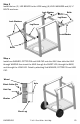
Step 3 Install the two (2) LEG BRACES to the LEGS using (8) LOCK WASHERS and (8) ½” BOLTS as shown. Bolts Lock Washer Leg Brace Lock Washers Leg Brace Lock Washer Bolts Step 4 Install one WASHER, COTTER PIN and HUB CAP onto the AXLE then slide the AXLE through WHEELS then insert the AXLE through the SHORT LEG, through the BASE, and through the LONG LEG. Finish by attaching 2nd WASHER, COTTER PIN and HUB CAP. Wheel Axle Black Cotter Pin Hub Cap Washer Short Leg OM3008 B.
Step 5 Attach the UPPER FRONT PANEL to the inside of the front LEGS using (4) LOCK WASHERS AND (4) 1/2” BOLTS. Then attach LOWER FRONT PANEL to the inside of the front LEGS using (4) LOCK WASHERS and (4) 1/2” BOLTS as shown below. Upper Front Panel Bolts Lock Washers Lock Washers Lower Front Panel Bolts Lock Washers OM3008 B.3 ™ & © Char-Griller / A&J Mfg.
Step 6 Attach the GRILL BODY to the CART using (8) LOCK WASHERS, (8) ½” BOLTS and four (8) FLAT WASHERS. Make sure to insert the bolt first through the lock washer then the flat washer then through the grill body. You may need to loosen other bolts and move the GRILL BODY slightly to get the holes in the GRILL BODY to line up with the holes in the LEGS. Lock Washers Bolts Flat Washers Step 7 Attach the SIDE SHELF with (4) ½” BOLTS and (4) LOCK WASHERS. Side Shelf Lock Washers Bolts OM3008 B.
Step 8 Install the CATCH PAN to the underside of the GRILL BODY by sliding it into the two slots on each end of the GRILL BODY. Make sure that the side of the CATCH PAN with the label “Wheel Side” is on the side of the grill with the wheels. From the rear of the grill, slide the GREASE TRAY into the guides/rails under the CATCH PAN.
Step 10 Install the CONTROL PANEL to the firebox. First plug the IGNITER WIRES to the Sockets on the back of the ELECTRONIC IGNITER, which is attached to the back side of the CONTROL PANEL. Any wire can go into any of the three sockets on the Electronic Igniter. Make sure the valve tips are completely inside the holes on the end of the BURNERS, see below. Then Secure the CONTROL PANEL with four (4) ½” BOLTS and four (4) LOCK WASHERS.
Step 11 Install the SIDE BURNER BODY to the firebox. Attach with four (4) ½” BOLTS and four (4) LOCK WASHERS. The BOLTS will first go through LOCK WASHERS, the GRILL BODY and then screw into the SIDE BURNER BODY. Side Burner Body Lock Washers Bolts Step 12 Attach the HOOD to the GRILL BODY using the HINGE PINS as shown below. First place the HOOD onto the GRILL BODY then screw the HINGE PINS into place and then insert COTTER PINS through the holes in the HINGE PINS on the inside of the GRILL BODY.
Step 13 Attach the HOOD HANDLE to the HOOD by inserting the HANDLE POSTS on each end of the HANDLE through the holes on the HOOD, the holes on the heat shield, and the LOCK WASHERS then secure the HANDLE with (2) WING NUTS as shown below. Attach THERMOMETER to the HOOD by inserting the THERMOMETER through the BEZEL and HOOD then secure it with (1) WING NUT as shown below. Tighten all bolts and nuts. Hood Thermometer Bezel Handle Wing Nut Lock Washers Heat Shield OM3008 B.3 ™ & © Char-Griller / A&J Mfg.
Step 14 Place the POT STAND over the SIDE BURNER. Place the FLARE-UP SHIELDS over the BURNER TUBES. Pot Stand Flare-Up Shields Step 15 Before attaching WARMING RACK you must attach the warming rack BOLTS to the GRILL HOOD and BODY. Insert the 1½” BOLTS through the holes in the sides of the HOOD from the outside and tighten the HEX NUTS on the inside of the HOOD. Insert the 1½” BOLTS through the holes in the sides of the GRILL BODY from the outside and tighten the HEX NUTS on the inside of the GRILL BODY.
NOTE: Hoses must go under and to the outside of the leg brace. Step 16 1. Place a standard 20 lb. LP gas cylinder (not included) into the cart assembly and connect the cylinder with the gas hose/regulator as shown. (See “Operating Grill” on page for further instructions). 2. Turn the Screw on the left side of the base panel clockwise to secure the standard 20 lb. LP gas cylinder.
Fully Assembled Caution: Use only the regulator provided! If a replacement is necessary, please call our customer service department, 912638-4724. Do NOT use replacement parts that are not intended for this grill. Hint: The paper label that is affixed to the hood is more easily removed when the hood is warm. Any remaining glue residue can be cleaned off with a spray lubricant like WD-40 . Do NOT use any other type of solvent or cleaner because this will damage the finish/paint/coating on the grill.
Connecting Gas Cylinder: The propane gas supply cylinder to be used must be constructed and marked in accordance with the Specifications for propane gas Cylinders of the U.S. Department of Transportation (DOT), or the National Standard of Canada, CAN/CSA B339, Cylinders, Spheres and Tubes for Transportation of Dangerous Goods; and Commission, as applicable. Only cylinders with a listed overfill prevention device (OPD) and marked “propane” may be used.
Cleaning and Care Caution: All cleaning and maintenance should be done when grill is cool and with the gas supply turned off at the propane cylinder. DO NOT clean any grill part in a self cleaning oven. The extreme heat will damage the finish. Cleaning Burning-off the grill after every use (approx. 15 minutes) will keep excessive food residue from building up. Clean grease tray and cup after EVERY use.
Cleaning the Burner Assembly • Remove grease collector. • Remove cooking grates and heat shield. • Remove burner by unscrewing nut from beneath burner “foot” using a screwdriver a pliers. • Lift burner up and away from gas valve orifice. • Clean inlet (venturi) of burner with small bottle brush or compressed air. • Remove all food residue and dirt on outside of burner surface. • Clean any clogged ports with a stiff wire (such as an opened paper clip) • Inspect burner for any damage (cracks or holes).
Stand in front of the grill to operate the controls. Note: Before starting the grill, check for leaks. Make sure the regulator valve is securely fastened to the burner and the cylinder. To prevent fire or explosion hazard when testing for a leak: 1. Always perform the “leak test” as described below before lighting the grill or each time the cylinder is connected for use. 2. Do not smoke or allow other sources of ignition in the area while conducting a leak test. 3.
Lighting Your Grill Danger: Failure to open hood while igniting the grill or not waiting 5 minutes to allow the gas to clear if the grill does not light, may result in an explosive flare-up which can cause serious bodily injury or death. Before cooking on this grill for the first time, operate the grill for about 15 minutes with the lid closed and the gas turned on “high”. This will “heat clean” the internal parts and dissipate odor from the manufacturing processes and painted finish. Main Burners: 1.
Side Burner 1. Open lid during lighting. Lid must be open when burner is on. 2. Burner valves must be in the “off” position. 3. Open cylinder valve. 4. Push in side burner valve knob fully and rotate slowly about ¼ turn counterclockwise until a click is heard. If the burner does not light, immediately turn the valve knob to OFF. Wait 5 minutes for the gas to clear and repeat the procedure. After burner ignites, adjust valve knob to desired cooking setting. Shutting Off Burners: 1.
Lighting Burner With a Match: 1. Place a match in the end of the match holder that is installed on the side of Grill Housing. Once lit, immediately place the flame through the cooking grates as shown near the burner ports. 2. Press in knob and rotate counter-clockwise to the High setting and burner should light immediately. 3. Adjust burners to desired cooking settings Cooking Grate Match Holder OM3008 B.3 Chain ™ & © Char-Griller / A&J Mfg.
Gas Grill Trouble Shooting Problem Possible Cause Burner will not light Wires/or electrode covered with cooking resiusing knobs due. Electrode and burners are wet. Burner will not light with match. Sudden drop in gas flow or reduced flame height. Irregular flame pattern, flame does not run the full length of burner. OM3008 B.
Gas Grill Troubleshooting, continued Possible Cause New burner may have residual Manufacturing oils. Prevention/Cure Insect nests in venturi. Clean venturi. Food residue, grease or seasoning salt on burner. Clean burner. Poor alignment of valve to burner venturi. Assure burner venturi is properly engaged with valve. High or gusting winds Turn front of grill to face wind or increase flame height.
GRILL PREPARATION & OPERATING INSTRUCTIONS PLEASE NOTE: NO RETURNS ON USED GRILLS Read all safety warnings and instructions carefully before assembling and operating your grill. 1. Note: The interior of the grills are not painted, they are coated with vegetable oil. DO NOT remove this coating. Cure grills prior to cooking to protect the interior and exterior finishes and prevent adding unnatural flavors to your food.
GRILLING RECIPES DIRECT METHOD STEAK (& ALL MEATS): Cook food directly above coals/heat. Generally speaking, to grill meats, raise fire grate to high position (hot) and sear for one minute on each side with the lid open to seal in flavor and juices. Then lower fire grate to medium position with lid closed and cook to desire doneness. Control heat with dual dampers and adjustable fire grate.
KABOBS: Alternating on skewers any combination of meat, onions, tomatoes, green peppers, mushrooms, zucchini, circular slice of corn-on-the-cob, or pineapple. Meat could consist of chunks of shrimp, scallops, lobster, chicken, sausage, pork, beef, etc. Marinate the meat in refrigerator for several hours. Grill each side approximately 7 minutes turning occasionally while basting with marinade. Leave a small amount of room between pieces in order to cook faster.
Page intentionally left blank for notes OM3008 B.3 ™ & © Char-Griller / A&J Mfg.
Page intentionally left blank for notes OM3008 B.3 ™ & © Char-Griller / A&J Mfg.
P.O. Box 30864 Sea Island, GA 31561 912-638-4724 www.CharGriller.com Warranty Information – Gas Grill Char-Griller® will repair or replace any defective part of its grillers/ smokers for a period of up to one year from the date of purchase. Char-Griller® will also repair or replace the body (lid and bottom half) of its grillers/smokers if the metal is rusted through or burned through for a period up to five years.