OWNER’S MANUAL Cheetah 1, Cheetah 2, Cougar 1, Cougar 2, CX 1, CX 2 Original Manual Keep in a safe place for later reference www.chariotcarriers.com DANGE R You should not use the Chariot child carrier before you have read and understood the contents of this Owner’s Manual. Failure to follow this warning may result in serious or fatal injury.
„Zwei plus zwei“ Marketing GmbH Stolberger Straße 1 D-50933 Köln Telefon: +49 - 2 21 - 95 14 70 - 0 Telefax: +49 - 2 21 - 95 14 70 - 20 E-Mail: info@zweipluszwei.com „Zwei plus zwei“ Marketing GmbH retains all rights to this Owner’s Manual. No texts, details or illustrations from this Manual may be either reproduced or distributed, or indeed become the subject of unauthorised use for commercial purposes, nor may they be made available to others.
1. General Items Intended Use Congratulations on buying this child transporter! Use as intended You have decided to buy a product from the CTS-series (Child Transport System) of the Canadian manufacturer Chariot Carriers Inc. Your new child transporter stands out because of its excellent quality, user-friendliness, high safety standards and great versatility.
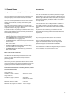
2. Overview of Components 3. Safety DANGE R The purpose of this section is to acquaint you with the symbols and safety instructions and make you aware of general dangers that might arise in using the carrier. In addition, here you will get to know about the particular dangers when using the carrier in road traffic, as well as being warned against unauthorised rebuilds or modifications.
3.2 General safety instructions As regards the children in the carrier Basics • When converting with other CTS Conversion Kits, no child should be sitting in the carrier, nor when carrying out maintenance or repair work. • The permitted total cargo load of the carrier is limited to 34 kg / 75 lb on the single-seater and 45 kg / 100 lb on the two-seater. This must never be exceeded. The cargo load is the weight of the children together with any luggage there might be.
3.4 Safety instructions for carrying infants 4. Description of the Ready Chassis • Children who cannot as yet sit up without support may only be carried using the Chariot infant Sling (accessory). • The Manufacturer accepts no liability for use of other sitting aids or baby seats. • Please make sure you follow the safety instructions in the Chariot Infant Sling Owner’s Manual 4.1 Supplied as standard Cheetah 1, Cheetah 2, Cougar 1, Cougar 2 3.
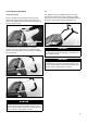
4.2 Assembly and folding up Assembling the Ready Chassis The assembly of the CX requires particular attention. Care needs to be taken here that the brake cable (see Section 3.10) is not bent or damaged in some other way. It must run along the frame tubes as illustrated. Push down the axle socket with your left hand, and at the same time push up the left frame tube using your right hand. Then pull the short lower side tube backwards with your left hand, pressing against it from above with your right hand.
Folding up the Ready Chassis 4.3 Wheel assembly When folding the CTS Ready Chassis up, the procedure is the reverse of the above: First pull or release the auto-lock disk on one side and push the short lower side tube slightly forwards. Repeat this procedure on the other side. Push the short lower side tube fully forwards. The wheels of the Chariot models described are fitted with so-called push-button axles.
4.4 Installing the handlebar CX Cougar and Cheetah The handlebar of the CX is installed in the same manner as described in the section above. Only one position is possible however, as the ergonomic five-position CX handlebar allows it to be gripped in various height positions, depending on use. Push the handlebar into the upper frame open tube ends. Depress both spring buttons simultaneously and push both ends of the handlebar at the same time into the tube ends until the spring buttons engage.
Handlebar bag (CX) The Chariot CX is equipped as standard with a handlebar bag, which can also be used as a child backpack. For the other models the handlebar bag can be purchased as an accessory. The handlebar bag is attached to a specially designed buckle at the upper rear end of the passenger compartment, as well as to the handlebar itself by means of two straps with buckles. 4.
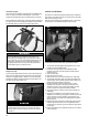
12. On each side of the buckle, the waist belt has a loose belt end for adjusting to fit correctly on the child. Adjust the waist belt until it is tight and the buckle is in the centre in front of the crotch belt. 13. Finally check that all belts are tight. However, avoid putting too much pressure on the child’s body. 14. Make sure that the padded shoulder harness’s belt position is correctly adjusted, as described below. M: Sleeve through both webbing loops. This is the default setting.
DANGE R Before each journey check all buckles. If this is not done, the belt system may fail in the event of an emergency, with the serious consequences mentioned above. DANGE R Always take particular care that the shoulder harness is correctly adjusted for height, as described above. In the event of an emergency, incorrect adjustment of the shoulder harness can result in the child getting strangled. Comparison of different adjustments of the padded shoulder harness for children of different heights.
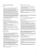
4.6 Climate control Opening the two-in-one weather cover: The two-in-one weather cover First undo the outer tabs of the assembly at both velcro fasteners. Then lift the two-in-one weather cover upwards, pulling equally on both of its tabs. All models are equipped with the Chariot two-in-one weather cover, which consists of a plastic window that can be rolled up with mesh beneath it. T IP On the Cougar and CX, make sure the upper corners rubber seal of the two-in-one weather cover is properly seated.
At low temperatures the sunscreen can be unrolled, flipped back, and inserted in the mesh pocket behind the seat (see Section 4.7). This reduces penetration of cold air through the mesh parts of the seat backrest. Side window on the CX For additional ventilation of the interior, the CX is equipped with removable side windows. These are each attached by 2 zippers and may be removed and stored in the rear storage bag.
Note: The floor covering of the Chariot Sport models Cheetah, Cougar, and CX forms the seat cover too. This special construction allows there to be a particularly low centre of gravity and generous head room. Using the Chariot in protracted heavy rain, and/or during longer journeys in the rain, causes saturation of the external skin. In unfavourable cases, moisture can penetrate the seat area, making it necessary for the children to wear suitable clothing. 4.
The bracket of the adjustable storage bag support bar has two settings, an upper and a lower one. Make sure that the storage bag engages properly in both positions. Before you change the position of the storage bag, you must release the quick-release skewers on each of the side brackets. Once you have changed the position, you must once again tighten the quick-release skewers. 4.8 Adjusting the suspension (Cougar and CX) The Cougar and CX are equipped with adjustable suspension.
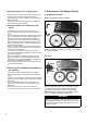
4.9 Operating the parking brake (Cheetah and Cougar) 4.10 1.1 CX brake system owner’s manual The parking brake of the Cheetah and Cougar is in the centre of the long cross axle under the rear lower storage bag. The brake system is in the form of a cable-operated drum brake working on both rear wheels. Lock the brake by depressing the brake lever with your foot.
DANGE R On inclines a maximum speed of 5 km/h / 3 mph is prescribed, otherwise there is a risk of the brakes overheating leading to possible brake failure. The maximum permissible speed for using the brake system with the carrier on level stretches is 15 km/h / 9 mph. Do not touch the brake drum at the wheel centre after a long period of use, as the brake drums can become hot and there is a risk of getting burnt.
Squeeze the brake lever hard in the direction of the handlebar grip until the locking pushbutton can be pushed in without encountering any appreciable resistance. Push it in until it locks. Adjusting the brake system Your Authorized Chariot Carriers will hand the carrier over to you with a fully adjusted brake system. Inevitable wear on the brake pads eventually leads to the brake lever having to be pulled closer and closer to the hand grip so as to obtain the braking force required.
The brake system involves the use of 3 adjusting screws: Case 1: Too much increase in brake lever play: First check that all brake cables with their end caps are properly located in the relevant hole of the adjusting screws. If necessary do the same for the adjusting screw on the brake lever (the one that you are not to adjust). wrong One on the brake force distributor (G1), and one on each of the drum brakes (G2, G3). By unscrewing G1, the inner cable in the top brake cable is tightened.
Case 2: Brakes pull unequally Fine adjusting Basic adjustment With a loaded carrier, check that the breaks now work with equal force and the carrier does not pull to one side on braking. First check that all brake cables with their end caps are properly located in the relevant hole of the adjusting screws. If necessary do the same for the adjusting screw on the brake lever (the one that you are not to adjust). (See illustration in the preceding section). 1.
Wheel removal Fitting this cap is particularly important when you are using the XC skiing kit. TIP When removing the wheels, the parking brake must be off. Ensure too that all brake cables with their end caps are properly located in the relevant hole of the adjusting screws. If necessary do the same for the adjusting screw on the brake lever (the one that you are not to adjust). To remove the wheel press the unlocking button in the centre of the wheel and pull the wheel off to the side.
Care and maintenance Cleaning The brake internal areas must be dry and free of dirt. If the wheels are removed, the protective cap prevents dirt entering from outside. Wear of the brake callipers, however, also gives rise to dust that clogs the inside. If necessary, please clean using a dry and grease-free brush. If you want to wash your Chariot with water, please leave the wheels in place, so that as little water as possible gets into the drum brakes.
5. The Cycling Kit As an alternative to the “Chariot” Cycling Kit, the Cycling Kit can be supplied with the Weber hitcharm and hitch. “Weber” Cycling Kit: Weber hitcharm without hitch, front, rear and spoke reflectors, safety flag. You can either choose the Weber hitch with adjustable kickstand (Weber B) or the Weber hitch for rear-axle attachment (Weber E).
As regards the children carried Performance characteristics when used as a Bicycle Trailer • For riders of bicycles and children being carried who can sit without support, we recommend wearing a suitable approved helmet. Top speed 25 km/h / 15 mph As regards the trailer Top speed on corners walking pace • When the trailer is towed behind a bicycle, the stroller wheels must never be fixed in their use position (wheels down). They may only be carried in their out-of-use position (wheels up).
Assembly For the plastic wheels used on theCheetah. Assembling the reflectors and safety flag Screw two reflectors onto each wheel on the brackets provided. If you want to use your Chariot as a Bicycle Trailer, all reflectors and safety flags must be installed. Exception: If you use tires with reflective strips, the spoke reflectors can be left off. Position a spoke reflector between two outer spokes and an inner spoke in such a way that the inner spoke lies in the guide slot of the reflector.
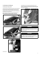
Screw the red reflectors into the rear grommets on the storage bag. Attaching the hitcharm to the CTS Ready Chassis The hitcharm is attached to the CTS Ready Chassis into the left “VersaWing 2.0” bracket. The hitcharm must always be attached into the left-hand side of the carrier (as seen in the direction of travel). The hitcharm must always be attached with both spring buttons pointing upwards. Press down the small button and slide the hitcharm into the VersaWing 2.
The hitcharm should now protrude about 2 cm / 3/4 inch out of the rear side of the VersaWing 2.0, and the rear vertical holes in the VersaWing 2.0 and hitcharm must align with each other. Correctly installed hitcharm. DANGE R Insert the security pin into the rear vertical hole of the VersaWing 2.0 and push it down completely through the hitcharm until the retaining ring is touching the top of the VersaWing 2.0. Make sure that the hitcharm is correctly attached and secured to the carrier.
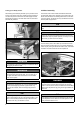
Attaching the Axle-Mount ezHitch The Axle-Mount ezHitch must always be attached to the left-hand side of the bicycle (as seen in the direction of travel). Bicycle with quick-release axle Remove the existing quick-release. Loosen the nut of the Chariot quick-release. Push the quick-release axle through the hitch and then through the axle of the wheel. The opening for the hitch ball and the vertical hole for the security pin must point forward.
Attaching the carrier Secure the pin by pulling the hole of the rubber tab over the protruding end of the pin. From the front, insert the elastomer ball, which is attached to the hitcharm, into the Axle-Mount ezHitch. Pull the hitch ball rearward to the end of the socket in the axle mounted hitch cup. 1 4 2 5 Push the security pin from the top through both holes of the Axle-Mount ezHitch. Finally, always attach the hitch’s back-up safety strap around the bicycle frame.
DANGER Always attach the hitch’s back-up safety strap in the manner described above. It serves as additional protection against losing the carrier during operation. DANGER Do not use the Bicycle Trailer if you cannot attach the hitch’s back-up safety strap around your bicycle frame for any reason! Contact your specialist retailer for assistance if this occurs. Special features of the VersaWing 2.
DANGER Always attach the snap hook of the hitch back-up safety strap to its accompanying D-ring on the hitcharm end that now points upwards. If you do not do this, it could get caught in the wheel spokes and cause an accident. Suitability of the bicycle used for towing Always make sure you follow the manufacturer’s specifications in the owner’s manual of the bicycle used for towing, where the suitability specifications of the bicycle are to be found.
Pay attention to the following when travelling: Follow all safety instructions at the beginning of this section and the general safety instructions at the beginning of the Owner’s Manual. DANGER When turning round or manoeuvring the outfit, the angle between the towing bicycle and the carrier must not exceed 90°, The hitch ball may get damaged (overstretched) and lose its stiffness as a result. DANGE R Make sure the spring button engages correctly.
6. The Jogging Kit The assembled Jogging Stroller (CTS Ready Chassis + Jogging Kit) Supplied as standard Jogging Kit: 16” wheel with quick-release skewer, and 2 wheel arms with ezClick attachment Safety instructions for use as a Jogging Stroller • Please make sure you read the safety instructions in the “Safety” section at the beginning of this Owner’s Manual.
Performance characteristics when used as a Jogging Stroller Top speed on straight aways 15 km/h / 9 mph Top speed on corners walking pace Top speed on hills/inclines walking pace Assembly Push the wheel arms, with the bend toward the centre of the carrier and wheel dropouts pointing downwards, into each VersaWing 2.0. The wheel arm should nowprotrude about 2 cm / 3/4 inch out of the rear side of the VersaWing 2.0.
Guide the quick-release axle through the wheel axle and screw on the nut. Both skewer springs must be located on each side so that the narrow side points towards the centre of the hub. Close the quickrelease lever. In order to ensure that the hub is clamped sufficiently in the axle dropouts, the quick-release lever must begin gripping as it moves from the open to the middle position, and approaching the closed position you should clearly feel resistance as you tighten.
DANGE R To correct directional trueness (ie. The carrier not rolling straight): Always make sure that the large spring button of each wheel arm engages in the hole of the relevant Click ‘n’ Store bracket. If this is not done, the wheel arm might work loose and get caught in the wheel spokes. You run the risk of an accident! The dropouts of the wheel arms are screwed on and their holes are slotted. After loosening both screws, the dropout can be moved.
Weight distribution 7. The Strolling Kit DANGER So as to prevent it from tipping backwards, the storage bags at the rear of the carrier may not be loaded with excessive weight. Carry out the following check: Push downwards on the handlebar by about 150 mm. The carrier should return to its original standing position and should not tip backwards. Manufacturer’s recommendation: There should be a maximum load of 4 kg in all the rear storage bags together if no handlebar bag is being used.
Safety instructions for using the brake system on the CX 1 and CX 2 models: • Before using the brake system for the first time, acquaint yourself with its braking effect. • On your first journeys always take the Owner’s Manual with you in case adjustments need to be made to the brake system. • Check the braking effect before each journey. • Before each journey check that both brakes operate with the same force. • Before each journey check that the lock nuts are tight on the adjusting screws.
If you want to convert the carrier from Stroller to another CTS Conversion Kit, you can store the stroller wheels on the top of the VersaWing 2.0 . To attach them proceed as described above. The caster fork arms should point backwards. Weight distribution DANGE R So as to prevent it from tipping backwards, the storage bags at the rear of the carrier may not be loaded with excessive weight. Carry out the following check: Push downwards on the handlebar by about 150 mm.
8. The Hiking Kit Assembly Lay both the hiking arms with shoulder harness and waist strap as shown in the “Supplied as standard” illustration in front of the carrier. The waist strap must be attached to the insides of both arms. Insert each arms into the VersaWing 2.0 until the vertical holes in the arms and VersaWing 2.0 are aligned with each other. The arms should now protrude about 2 cm / 3/4 inch out of the rear side of the VersaWing 2.0.
The shoulder strap, which is attached in a similar way to that of a backpack, can be adjusted in three positions: at the chest strap at the front, at the back strap on top for adjusting the height of the waist strap and at the waist strap itself. TIP The holes in the hiking arms are larger than the security pins, so that the arms can rotate slightly around their longitudinal axes (in order to adapt to narrow or wide hips, and single and double width carriers).
9. The XC Skiing Kit The assembled XC Skiing Carrier (CTS Ready Chassis + Skiing Kit) Supplied as standard Skis with frames, ski arms with waist belt, additional self-locking nuts Safety instructions for use as an XC Skiing Carrier • Please note: For the CX 1 and CX 2 models there is a special XC Skiing Kit. • The XC Skiing Kit of the other models does not fit because the axle is too short.
Assembly CX Attaching the skis to the carrier To attach the XC Skiing Kit to the carrier, first remove the carrier wheels. Then attach the clear protective caps over the exposed drum brake calipers. Cheetah und Cougar Remove the wheels (for this, press the rubber cap in the centre of the wheel). To attach the skis, press the spring button in and insert the attachment axle into the axle socket until it can go no further. Release the spring button.
Pressing down the locking button on the axle, insert the XC Skiing Kit into the axle socket on the Chariot CX until it can go no further. Release the locking button. The axle will now click if installed fully. Make sure the skis are inserted correctly with the ski tips towards the front of the carrier. Now secure the arms by inserting the security pin from above through the vertical hole in the arm and VersaWing 2.0 until it stops.
Length adjustment of the ski arms The ski arms are adjustable for length. To do this, withdraw the security pin which connects the two ski arm tubes. If required, the waist belt can be adjusted for larger and smaller hips. To do this, undo both attachment screws and reinstall them into the appropriate grommets. When refitting the screws, always use the additional self-locking nuts supplied. Move both tubes towards each other until the desired holes in both tubes align with each other.
10. The Walking Kit The assembled Walker (Ready Chassis + Walking Kit) Supplied as standard Fitting the drawbars to the carrier Identical for all models. Insert each drawbar into the VersaWing 2.0 until the vertical holes in the arms and VersaWing 2.0 are aligned with each other. The drawbars should now, at the back in the slot of the VersaWing 2.0, protrude about 2 cm / 3/4“ over the plastic edge.
Now secure the drawbars by inserting the security pin from above through the vertical hole in the arm and VersaWing 2.0 until it stops. Lock the security pin by looping the spring clip over the pins end that protrudes underneath the VersaWing 2.0. Putting on the waist belt Always put the waist belt on so that the padded area is at the back and the strap with its side-release buckle is at the front.
11. Accessories Fabric Travel Bag Axle-Mount ez-Hitch for additional bike Storage Cover Rain Cover Infant Sling Baby Bivy Baby Supporter Bunting Bag X-Country Cargo Rack Check the fabric regularly for signs of damage (e.g. tears). DANGE R Tears in the fabric actually represent a high safety risk. Due to tears in the fabric, your child could come into contact with the wheels or the road surface. Contact your authorized Chariot retailer immediately if you find a tear in the fabric.
13.
www.chariotcarriers.