
Technical Specifications


107
INSTALLATION PROCEDURES
3. The pipe should be surrounded with an aggregate material
which can be easily worked around the sides of the pipe.
Backfilling should be performed in layers of 6 inches with
each layer being sufficiently compacted to 85% to 95%
compaction.
4. A mechanical tamper is recommended for compacting
sand and gravel. These materials contain fine-grains such
as silt and clay. If a tamper is not available, compacting
should be done by hand.
5. The trench should be completely filled. The backfill should
be placed and spread in uniform layers to prevent any
unfilled spaces or voids. Large rocks, stones, frozen clods,
or other large debris should be removed. Stone backfill
shall pass through an 1-1/2” sieve. Heavy tampers or
rolling equipment should only be used to consolidate the
final backfill.
6. To prevent damage to the pipe and disturbance to pipe
embedment, a minimum depth of backfill above the pipe
should be maintained. Pipe should always be installed
below the frost level. Typically, it is not advisable to
allow vehicular traffic or heavy construction equipment
to traverse the pipe trench.
Note: This section is a general reference guide and should
not be considered a complete engineering resource addressing
all aspects of design and installation of pipe in buried
applications. Charlotte Pipe recommends that a design
professional use this manual along with other industry
references, taking into account sub-surface conditions
unique to each project, and that all installations be made in
accordance with the requirements found in ASTM D 2321
and in compliance with applicable code requirements.
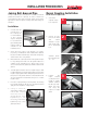
Gasketed Pipe Assembly*
Bar and block is the recommended method of assembly.
Small-diameter pipes can be assembled by one worker, while
larger diameters may require two people working together.
Besides quicker installation of a pipe line, the major advantage
of barring pipe (see Bar & Block illustration below) is that
the worker has a feel for the process. This assures proper
alignment and assembly.
NOTE: Assembly with power equipment is not recommended.
Standard good mechanical assembly practice take alignment
into consideration and produces reliable, leak-free pipe lines.
Straight alignment assembly will not dislodge gaskets.
Forced, improper alignment insertion produces an insertion
curve characterized by the tremendous force necessary
to dislodge the gasket from the race, trap it between the
bell and spigot surfaces, and stretch it backwards. The
insertion force necessary to assemble a joint with dislodged
gaskets is so extreme, it can only be accomplished using
mechanical equipment without the operator’s knowledge of
the dislocation.
Joint Insertion Instructions
1. Clean the gasket area. Remove sand, dirt, grease, and
debris. Do not remove gaskets from bells.
2. Check the gasket. Make sure it is seated uniformly in
the groove by running your finger around the inner edge
of the gasket. If the gasket has a plastic retainer ring,
make sure it it’s properly seated into the rubber portion
of the gasket.
3. Clean the spigot. Use a rag to wipe the spigot clean.
4. Lower the pipe into the trench carefully to avoid getting
dirt onto the bell or spigot.
5. Lubricate. Apply approved pipe lubricant to the bevel of
the spigot end and approximately mid-way back to the
reference line. A thin layer of lubricant may be applied to
the face of the gasket, but be careful not to get lubricant
behind or under the gasket.
6. Keep lubricated areas clean. If dirt or sand adheres to
lubricated areas, clean and re-lubricate.
7. Assemble pipe. Insert the spigot end into the pipe until
it contacts the gasket uniformly or is a short distance
from the gasket. Straight alignment is essential. Apply
steady pressure by hand or by mechanical means (bar
and block, come-along, hydraulic jack) until the spigot
slips through the gasket. Insert pipe until the assembly
stop line is flush with the bell end.
8. If undue resistance to pipe insertion is encountered or
if the pipe cannot be inserted to the reference mark,
disassemble the joint and check the position of the gasket.
If the gasket is still properly positioned, verify proper
positioning of the reference mark. Relocate the mark if
it is not correctly positioned. In general, fittings allow
less insertion than do pipe bells.
9. If the pipe must be field-cut, mark the entire circumference
to ensure a square cut. Bevel the field cut the same as
a factory bevel. If being installed into fittings, follow
manufacturer’s recommendations. Round off any sharp
edges on the leading edge of the bevel with a pocket knife