
Installation Guide

94
Plastics Technical Manual
Pipe Size
In Inches
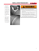
For systems where dismantling is required, flanging is a
convenient joining method. It is also an easy way to join plastic
and metallic systems.
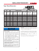
Flange
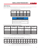
Tightening
Sequence
Installation
1. Join the flange to
the pipe using the
procedures shown in
the solvent cementing
or threading sections.
2. Use a full faced
elastomeric gasket
which is resistant to the chemicals being conveyed in the
piping system. A gasket
1
⁄8
”
thick with a Durometer, scale
“A”,hardnessof55-80isnormallysatisfactory.
3. Align the flanges and gasket by inserting all of the bolts
through the mating flange bolt holes. Be sure to use
properly sized at washers under all bolt heads and
nuts.
4. Sequentially tighten the bolts corresponding to the
patternsshownbelow.Newboltsandnutsshouldbeused
for proper torque.
5. Tighten flanges only to maximum recommended torque
limits;donottightenboltsinsuchamannerastocause
the flange ring to bend or be under stress. Connect to full
faceangesorvalvesthatconformtoANSIB16.5150
pound dimensions and that provide full support under the
entire flange face.
6. Use atorquewrenchto tightentheboltsto thetorque
values shown below.
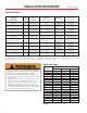
Recommended Torque
No. Bolt
Holes
Bolt
Diameter
Recommended
Torque ft/lbs
Note:Flangesmeetthebolt-patternrequirementsofANSI/ASMEB16.5
1
⁄2 4
1
⁄2 10 - 15
3
⁄4 4
1
⁄2 10 - 15
1 4
1
⁄2 10 - 15
1
1
⁄4 4
1
⁄2 10 - 15
1
1
⁄2 4
1
⁄2 10 - 15
2 4
5
⁄8 20 - 30
2
1
⁄2 4
5
⁄8 20 - 30
3 4
5
⁄8 20 - 30
4 8
5
⁄8 20 - 30
6 8
3
⁄4 33 - 50
8 8
3
⁄4 33 - 50
10 12
7
⁄8 53 - 65
12 12
7
⁄8 53 - 75
INSTALLATION PROCEDURES
7. Useofthreadlubricant
will ensure proper
torque. Confirm that
the thread lubricant is
chemically compatible
with pipe and fittings.
8. Wheninstallinganges
in a buried application
where settling could
occur, the flange must
Flanges
• Exceeding recommended flange bolt torque may result in
component damage, system failure and property damage.
• Use the proper bolt tightening sequence as marked on the
flange.
• Make sure the system is in proper alignment.
• Flanges may not be used to draw piping assemblies
together.
• Flat washers must be used under every nut and bolt head.
• Connect to full face flanges or valves that conform to ANSI
B16.5 150 pound dimensions and that provide full support
under the entire flange face.
• Exceeding recommended pressure rating and/or
temperature ratings may result in component damage,
system failure and property damage.
• Ensure that thread lubricant is chemically compatible with
pipe and fittings.
• Piping systems differ in chemical resistance. Pipe or fittings
may be damaged by contact with products containing
incompatible chemicals resulting in system failure and/or
property damage.
• Corrosion resistant bolts, nuts, and flat washers are
recommended in chemical applications.
System Operating Temp. 70 80 90 100 110 120 130 140 150 160 170 180 200
Temperature °F (C) (23) (27) (32) (38) (43) (49) (54) (60) (66) (71) (77) (82) (93)
PVC 150 132 113 93 75 60 45 33 NR NR NR NR NR
CPVC 150 144 137 123 116 98 93 75 70 60 48 38 30
Pressure Rating of PVC and CPVC Flanges at Elevated Temperatures
1
⁄2
”
- 12
”
Pressure
Rating (psi)
NR=NotRecommended
Testing with or use of compressed air or gas in PVC / ABS
/ CPVC pipe or fittings can result in explosive failures and
cause severe injury or death.
• NEVER test with or transport/store
compressed air or gas in PVC / ABS / CPVC
pipe or fittings.
• NEVER test PVC / ABS / CPVC pipe or
fittings with compressed air or gas, or air
over water boosters.
• ONLY use PVC / ABS / CPVC pipe or
fittings for water or approved chemicals.
• Refer to warnings in PPFA User Bulletin
4-80 and ASTM D 1785.
1
1
1
2
2
2
6
10
4
44
8
12
5
9
3 3
8
7
6
5
3
7
11
be supported to maintain proper alignment in service.