
How to Guide


59
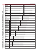
ABS, PVC and CPVC pipe, like other piping materials, undergo
length changes as a result of temperature variations above and
below the installation temperature. They expand and contract
4.5 to 5 times more than steel or iron pipe. The extent of the
expansion or contraction is dependent upon the piping material’s
coefficient of linear expansion, the length of pipe between
directional changes, and the temperature differential.
The coefficients of linear expansion (Y) for ABS, PVC, and
CPVC (expressed in inches of expansion per 10°F temperature
change per 100 feet of pipe) are as follows:
Material Y (in./10°F/100 ft)
ABS 0.66
ABS Plus 0.500
PVC 0.36
CPVC 0.408
The amount of expansion or contraction can be calculated
using the following formula:
∆L = Y (T1-T2) x Lp h
10 100
∆L = Dimensional change due to thermal expansion
or contraction (in.)
Y = Expansion coefficient (See table above.)
(in./10°F/100 ft)
(T1-T2) = Temperature differential between the
installation temperature and the maximum
or minimum system temperature, whichever
provides the greatest differential (°F).
L = Length of pipe run between changes in
direction (ft)
Example: How much expansion (e) can be expected in a
60 foot straight run of 2” diameter PVC pipe installed at
70°F and operating at 120°F?
Solution:
∆L = .360 (120 - 70) x 60 =.360 x 5 x .6 = 1.08 inches
10 100
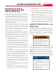
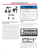
There are several ways to compensate for expansion and
contraction. The most common methods are:
1. Expansion Loops (Fig. 1)
2. Offsets (Fig. 2)
3. Change in direction (Fig. 3)
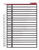
Modulus of Elasticity & Working Stress
ABS PVC CPVC
Modulus of Working Modulus of Working Modulus of Working
Elasticity Stress Elasticity Stress Elasticity Stress
(psi) (psi) (psi) (psi) (psi) (psi)
73° F 250,000 N/A 420,000 2,000 370,000 2,000
90° F 240,000 N/A 380,000 1,500 360,000 1,820
100° F 230,000 N/A 350,000 1,240 350,000 1,640
120° F 215,000 N/A 300,000 800 340,000 1,300
140° F 195,000 N/A 200,000 400 325,000 1,000
160° F N/A N/A N/A N/A 310,000 800
180° F N/A N/A N/A N/A 290,000 500
Modulus Data is Modulus of Elasticity in Tension per ASTM D 638
Table 1
Expansion Joints
A wide variety of products are available to compensate for
thermal expansion in piping systems including:
• Piston type expansion joints
• Bellows type expansion joints
• Flexible bends
The manufacturers of these devices should be contacted to
determine the suitability of their products for the specific
application. In many cases these manufacturers provide
excellent technical information on compensation for thermal
expansion. Information on these manufacturers and industry
standard may be obtained through the Expansion Joint
Manufacturers Association WWW.EJMA.ORG.
When installing an expansion loop, no rigid or restraining
supports should be placed within the leg lengths of the loop. The
loop should be installed as closely as possible to the mid-point
between anchors. Piping support guides should restrict lateral
movement and direct axial movement into the loop. Lastly, the
pipe and fittings should be solvent cemented together, rather
than using threaded connections.
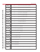
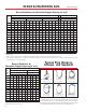
DESIGN & ENGINEERING DATA
Expansion and Contraction of
PVC Schedule 40, PVC Schedule
80, PVC PR 200 and PVC PR 160
Expansion Loop Formula
L = 3 ED (∆L)
2S
Where:
L = Loop length (in.)
E = Modulus of elasticity at maximum
temerature (psi) (Table 1)
S = Working Stress at maximum
temperature (psi) (Table 1)
D = Outside diameter of pipe (in.) (pages 22-34)
∆L = Change in length due to change in
temperature (in.)