
How to Guide

54
Plastics Technical Manual
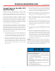
ABS, PVC and CPVC pipe, like other piping materials, undergo
length changes as a result of temperature variations above and
below the installation temperature. They expand and contract
4.5 to 5 times more than steel or iron pipe. The extent of the
FYQBOTJPOPSDPOUSBDUJPOJTEFQFOEFOUVQPOUIFQJQJOHNBUFSJBMT
coefficient of linear expansion, the length of pipe between
directional changes, and the temperature differential.
5IF DPFGmDJFOUT PG MJOFBS FYQBOTJPO: GPS"#4 17$ BOE
CPVC (expressed in inches of expansion per 10°F temperature
change per 100 feet of pipe) are as follows:
Material Y (in./10°F/100 ft)
ABS 0.66
PVC 0.36
CPVC 0.408
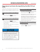
The amount of expansion or contraction can be calculated
using the following formula:
F :55Y-Q
h
10 100
F%JNFOTJPOBMDIBOHFEVFUPUIFSNBMFYQBOTJPO
or contraction (in.)
:&YQBOTJPODPFGmDJFOU4FFUBCMFBCPWF
JO×'GU
555FNQFSBUVSF EJGGFSFOUJBM CFUXFFO UIF
installation temperature and the maximum
or minimum system temperature, whichever
provides the greatest differential (°F).
-Q-FOHUI PG QJQF SVO CFUXFFO DIBOHFT JO
direction (ft)
&YBNQMF)PXNVDIFYQBOTJPOFDBOCFFYQFDUFEJOB
GPPUTUSBJHIUSVOPGwEJBNFUFS17$QJQFJOTUBMMFEBU
70°F and operating at 120°F?
Solution:
FYYYJODIFT
10 100
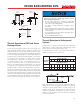
There are several ways to compensate for expansion and
contraction. The most common methods are:
1. Expansion Loops (Fig. 1)
2. Offsets (Fig. 2)
3. Change in direction (Fig. 3)
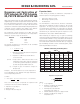
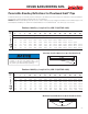
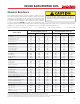
Modulus of Elasticity & Working Stress
ABS PVC CPVC
Modulus of Working Modulus of Working Modulus of Working
Elasticity Stress Elasticity Stress Elasticity Stress
(psi) (psi) (psi) (psi) (psi) (psi)
73° F 250,000 N/A 420,000 2,000 370,000 2,000
90° F 240,000 N/A 380,000 1,500 360,000 1,820
100° F 230,000 N/A 350,000 1,240 350,000 1,640
120° F 215,000 N/A 300,000 800 340,000 1,300
140° F 195,000 N/A 200,000 400 325,000 1,000
160° F 180,000 N/A N/A N/A 310,000 800
180° F N/A N/A N/A N/A 290,000 500
.PEVMVT%BUBJT.PEVMVTPG&MBTUJDJUZJO5FOTJPOQFS"45.%
Table 1
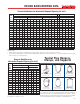
Expansion Joints
A wide variety of products are available to compensate for
thermal expansion in piping systems including:
t 1JTUPOUZQFFYQBOTJPOKPJOUT
t #FMMPXTUZQFFYQBOTJPOKPJOUT
t 'MFYJCMFCFOET
The manufacturers of these devices should be contacted to
determine the suitability of their products for the specific
application. In many cases these manufacturers provide
excellent technical information on compensation for thermal
expansion. Information on these manufacturers and industry
TUBOEBSE NBZ CF PCUBJOFE UISPVHI UIF &YQBOTJPO +PJOU
.BOVGBDUVSFST"TTPDJBUJPO888&+."03(
8IFO JOTUBMMJOH BO FYQBOTJPO MPPQ OP SJHJE PS SFTUSBJOJOH
supports should be placed within the leg lengths of the loop. The
loop should be installed as closely as possible to the mid-point
between anchors. Piping support guides should restrict lateral
movement and direct axial movement into the loop. Lastly, the
pipe and fittings should be solvent cemented together, rather
than using threaded connections.
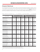
DESIGN & ENGINEERING DATA
Expansion and Contraction of
PVC Schedule 40, PVC Schedule
80, PVC PR 200 and PVC PR 160
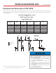
Expansion Loop Formula
-&%6L)
2S
8IFSF
- -PPQMFOHUIJO
& .PEVMVTPGFMBTUJDJUZBUNBYJNVN
temerature (psi) (Table 1)
4 8PSLJOH4USFTTBUNBYJNVN
temperature (psi) (Table 1)
% 0VUTJEFEJBNFUFSPGQJQFJOQBHFT
6- $IBOHFJOMFOHUIEVFUPDIBOHFJO
temperature (in.)