
How to Guide


96
Plastics Technical Manual
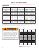
Pipe Size
In Inches
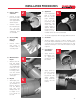
For systems where dismantling is required, flanging is a
convenient joining method. It is also an easy way to join plastic
and metallic systems.
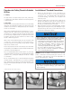
FLANGE BOLT TIGHTENING SEQUENCE
Installation
1. Join the flange to
the pipe using the
procedures shown in
the solvent cementing
or threading sections.
2. Use a full faced
elastomeric gasket which is resistant to the chemicals
being conveyed in the piping system. A gasket
1
⁄8
”
thick
with a Durometer, scale “A”, hardness of 55 -80 is
normally satisfactory.
3. Align the flanges and gasket by inserting all of the bolts
through the mating flange bolt holes. Be sure to use
properly sized at washers under all bolt heads and
nuts.
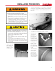
6. Useatorquewrenchto
tighten the bolts to the
torque values shown
below.
7. Useofthreadlubricant
will ensure proper
torque. Confirm that
the thread lubricant is
chemically compatible
with pipe and fittings.
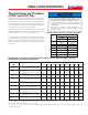
Recommended Torque
No. Bolt
Holes
Bolt
Diameter
Recommended
Torque ft/lbs
Note:Flangesmeetthebolt-patternrequirementsofANSI/ASMEB16.5
1
⁄2 4
1
⁄2 10 - 15
3
⁄4 4
1
⁄2 10 - 15
1 4
1
⁄2 10 - 15
1
1
⁄4 4
1
⁄2 10 - 15
1
1
⁄2 4
1
⁄2 10 - 15
2 4
5
⁄8 20 - 30
2
1
⁄2 4
5
⁄8 20 - 30
3 4
5
⁄8 20 - 30
4 8
5
⁄8 20 - 30
6 8
3
⁄4 33 - 50
8 8
3
⁄4 33 - 50
10 12
7
⁄8 53 - 75
12 12
7
⁄8 53 - 75
INSTALLATION PROCEDURES
4. Sequentially tighten the bolts corresponding to the
patternsshownbelow.Newboltsandnutsshouldbeused
for proper torque.
5. Ensure that the mating surfaces are in direct contact. A
gap between the flange face and mating surface may result
in flange failure. Do not connect to lug type appurtenances
without additional flange support.
Flanges
• Exceeding recommended flange bolt torque may result in
component damage, system failure and property damage.
• Use the proper bolt tightening sequence as marked on the
flange.
• Make sure the system is in proper alignment.
• Flanges may not be used to draw piping assemblies
together.
• Flat washers must be used under every nut and bolt head.
• Ensure that the mating surfaces are in direct contact. A gap
between the flange face and mating surface may result in
flange failure.
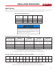
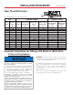
System Operating Temp. 70 80 90 100 110 120 130 140 150 160 170 180 200
Temperature °F (C) (23) (27) (32) (38) (43) (49) (54) (60) (66) (71) (77) (82) (93)
PVC 150 132 113 93 75 60 45 33 NR NR NR NR NR
CPVC 150 144 137 123 111 98 87 75 68 60 NR NR NR
Pressure Rating of PVC and CPVC Flanges at Elevated Temperatures
1
⁄2
”
- 6
”
Pressure
Rating (psi)
NR=NotRecommended