
How to Guide


55
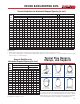
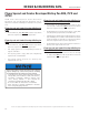
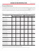
20 3.0 3.5 4.5 5.0 6.0 6.5 7.0 7.0 8.0 8.0
50 7.0 9.0 11.0 13.0 14.0 15.5 17.0 18.0 19.0 20.0
100 13.0 18.0 22.0 26.0 29.0 31.5 35.0 37.0 40.0 42.0
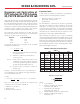
Secure above-ground vertical DWV or storm-drainage
piping at sufficiently close intervals to maintain proper
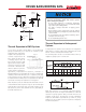
Figure 4
PistonTypeExpansionJointIllustrated
(CharlottePipePartNo.PVC133)
Compensation for expansion and contraction in underground
applications is normally achieved by snaking the pipe in the
trench. Solvent cemented joints must be used.
The following table shows recommended offsets and loop
lengthsforpipingupto3”nominalsize.
Max. Temp. Variation °F, Between Installation
and Final Operation
10° 20° 30° 40° 50° 60° 70° 80° 90° 100°
Loop Offset In Inches
Loop Length
In Feet
alignment and to support the
weight of the piping and its
contents. Support stack at
base, and if over two stories
in height, support stack at
base and at each floor with
approved riser clamps. Stacks
should be anchored so that
movement is directed to the
offset or expansion joint. For
vertical stacks in multi-story
applications, compensation for expansion, contraction or
building settling is recommended. This can be accomplished by
installingahorizontaloffset(Fig.2)orexpansionjoint(Fig.
4) at a minimum of every other floor. Expansion joints should
be installed in the neutral position. Compensation for thermal
movements is usually not required for a vent system.
Note:Expansionjointsarelubricated.Ifsandordirtcomesin
contact with the lubricant, the O-rings can become damaged
and leaks will result. Please keep clean until ready to use. If
the expansion joint is stuck and will not move, tap lightly to
break the lubricant seal.
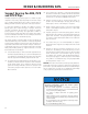
Thermal Expansion in DWV Systems
Thermal Expansion in Underground
Systems
DESIGN & ENGINEERING DATA
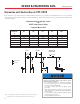
Change of Direction
Long Run of Pipe
Hanger or Guide
L
Restraint
2L/5
L/5 6”
MIN
6”
MIN
Loop
L
(Figure 1)
(Figure 3)
L
L /4
L/2
L/4
Offset
(Figure 2)
Failure to compensate for expansion and contraction
caused by temperature change may result in system
failure and property damage.
• Do not restrict expansion or contraction. Restraining
movement in piping systems is not recommended and
may result in joint or fitting failure.
• Use straps or clamps that allow for piping system
movement.
• Align all piping system components properly without
strain. Do not bend or pull pipe into position after being
solvent welded.
• Do not terminate a pipe run against a stationary object
(example: wall or floor joist).
• Do not install fittings under stress.
Note:This manual isnot a complete engineeringreference
addressing all aspects of design and installation of thermal
expansioninpipingsystems.Manyexcellentreferencesare
available on this topic. The American Society of Plumbing
Engineers (www.ASPE.org) Data Book, Volume 4, 2008,
Chapter 11 is an excellent resource for engineers on designing
for thermal expansion.