
How to Guide


49
Water Hammer
Water hammer is a term used to describe the sudden increase
in pressure created by quickly stopping, starting, or changing
the direction of the flow of fluid in a piping system. Typical
actions which cause water hammer are:
(1) Quickly closing a valve.
(2) Quickly opening a valve.
(3) Starting pumps with an empty discharge line.
(4) A high speed wall of liquid (such as starting a pump)
suddenly changes direction (such as going through a 90°
elbow).
(5) Moving entrapped air through the system.
The pressure increase generated must be added to the fluid
pressure already existing in the piping system to determine the
total pressure the system must withstand. CAUTION! If water
hammer is not accounted for, the sudden pressure surge could
be enough to burst the pipe, or break the fittings or valves.
Taking the following measures will help prevent problems:
(1) Keep fluid velocities under 5 feet per second for PVC and
8 feet per second for CTS CPVC.
(2) Use actuated valves with controlled opening and closing
speeds.
(3) Instruct operators of manual valves on the proper opening
and closing speeds.
(4) When starting a pump, partially close the valve in
the discharge line to minimize the volume of liquid
accelerating through the system. Fully open the valve
after the line is completely filled.
(5) Use a check valve in the pipe line, near the pump, to keep
the line full.
(6) Use air relief valves to control the amount of air that is
admitted or exhausted throughout the piping system.
(7) Design the piping system so that the total pressure
(operating plus water hammer surge) does not exceed
the pressure rating of the lowest rated component in the
system.
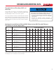
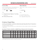
1. Liquid Velocity (feet/second), pipeline length (feet), and
valve closing time (seconds) must be known.
2. Place a straight edge on the liquid velocity in pipe (line
A) and the pipeline length (line D).
3. Mark intersection of straight edge with pivot line (line
C).
4. Place straight edge on mark just placed on pivot line (line
C) and on valve closing time for valve being used (line
A).
5. The intersection of the straight edge with the pressure
increase line (line B) is the liquid momentum surge
pressure (water hammer).
The liquid momentum surge pressure should be added to the
operating line pressure to determine the system’s maximum
line pressure. The maximum line pressure is used to select the
proper pipe schedule or wall thickness.
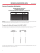
The nomograph is based on the formula
P = 0.070VL
T
where P is increase in pressure due to momentum surge in
psi, L is pipeline length in feet, V is liquid velocity in feet per
second, and T is valve closing time in seconds.
How To Use The Nomograph On The
Following Page:
DESIGN & ENGINEERING DATA