Cast Iron TECHNICAL AND INSTALLATION MANUAL (Updated November 6, 2012) © 2002-2012 Charlotte Pipe and Foundry Company TECHNICAL MANUAL TM-CI
INTRODUCTION Cast Iron Installation As the leading manufacturer of cast iron soil pipe and fittings, Charlotte Pipe and Foundry can be your one-stop source for all your cast iron piping system needs. We manufacture a full line of Service and Extra Heavy cast iron soil pipe and fittings from 2” - 15”, and Double-Hub pipe from 2” - 6”. We also manufacture a full line of No-Hub (hubless) pipe and fittings, 11/2” - 15”. All of our products are proudly made in the U.S.A.
TABLE OF CONTENTS GENERAL INFORMATION Page Introduction .......................................................................................................... 2 Understanding Safety Alert Messages .................................................................. 5 Components of the DWV System .......................................................................... 6 Performance .......................................................................................................
TABLE OF CONTENTS Cast Iron Installation INSTALLATION PROCEDURES FOR CAST IRON Cutting Methods for Cast Iron Soil Pipe ............................................................. 30 Cutting Cast Iron Soil Pipe with a Snap Cutter.................................................. 30 Joining Methods for Cast Iron Soil Pipe ........................................................ 31-34 Compression Gaskets........................................................................................
GENERAL INFORMATION Understanding Safety Alert Messages It is important to read and understand this manual. It contains information to help protect your safety and prevent problems. This is the safety alert symbol. It is used to alert you to potential personal injury hazards. Obey all safety messages that follow this symbol to avoid personal injury or death. “WARNING” Indicates a hazardous situation which, if not avoided, could result in severe injury or death.
GENERAL INFORMATION COMPONENTS OF THE DWV SYSTEM Engineers and designers have a number of materials from which to choose as they design sanitary and storm drainage systems for residential and commercial projects. Due to its exceptional strength and combination of being noncombustible and extremely quiet, cast iron soil pipe is a very popular choice for commercial construction.
GENERAL INFORMATION The pH range for typical DWV systems is between 4.5 and 7. We suggest that the installer establish a uniform slope for horizontal drainage piping, but not less than permitted by applicable plumbing code and in compliance with good plumbing practices, to facilitate flushing of the system. If operating conditions yield an acidity level of pH 4.3 or less, we recommend dilution of the waste stream to raise the pH.
GENERAL INFORMATION Soundproofing Qualities of Cast Iron Systems One of the most significant features of cast iron pipe, compression gaskets and hubless couplings is their sounddeadening quality. The problem of noise is particularly acute in multi-family housing. Although soundproofing has become a major concern in construction design, certain plumbing products have been introduced that not only transmit noise, but may actually amplify it.
GENERAL INFORMATION Gray Iron Physical Properties Composition of Gray Iron Tensile Strength 20,000 p.s.i. — 60,000 p.s.i. (21,000 p.s.i.) The following are typical ranges of elements present in unalloyed gray cast iron normally produced in commercial practice: Elastic Modulus (Young’s modulus) 10 - 23 x 106 p.s.i. Hardness (Brinell) Thermal Conductivity Carbon (C) 2.60 - 3.85% Silicon (Si) 1.25 - 2.90% Manganese (Mn) 0.40 - 1.00% Phosphorus (P) 0.02 - 0.90% Sulfur (S) 0.04 - 0.
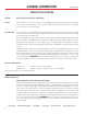
GENERAL INFORMATION Cast Iron Installation PRODUCT SPECIFICATION System: Service Cast Iron Soil Pipe and Fittings Scope: This specification covers Service Cast Iron pipe, fittings, and compression gaskets used in sanitary drain, waste, and vent (DWV), sewer, and storm drainage applications. This system is intended for use in non-pressure applications. Specification: Service Cast Iron pipe and fittings shall be manufactured from gray cast iron with a tensile strength of not less than 21,000 psi.
GENERAL INFORMATION PRODUCT SPECIFICATION System: Extra Heavy Cast Iron Soil Pipe and Fittings Scope: This specification covers Extra Heavy Cast Iron pipe, fittings, and compression gaskets used in sanitary drain, waste, and vent (DWV), sewer, and storm drainage applications. This system is intended for use in non-pressure applications. Specification: Extra Heavy Cast Iron pipe and fittings shall be manufactured from gray cast iron with a tensile strength of not less than 21,000 psi.
GENERAL INFORMATION Cast Iron Installation PRODUCT SPECIFICATION System: Hubless Cast Iron Soil Pipe and Fittings Scope: This specification covers hubless Cast Iron pipe, fittings, and couplings used in sanitary drain, waste, and vent (DWV), sewer, and storm drainage applications. This system is intended for use in non-pressure applications. Specification: Hubless Cast Iron pipe and fittings shall be manufactured from gray cast iron with a tensile strength of not less than 21,000 psi.
GENERAL INFORMATION PRODUCT CERTIFICATION Specifications Charlotte® Cast Iron Soil Pipe and Fittings This is to certify that all cast iron pipe and fittings manufactured by Charlotte Pipe and Foundry are made in the United States and conform to the following standards: SERVICE HUB AND SPIGOT PIPE AND FITTINGS All cast iron soil pipe and fittings shall be marked with the collective trademark of the Cast Iron Soil Pipe Institute. ASTM A 74 ANSI A 112.5.
GENERAL INFORMATION Cast Iron Installation Service Cast Iron F 1/8 S R G Testing with or use of compressed air or gas in Cast Iron pipe or fittings can result in explosive failures and cause severe injury or death. P T Y A J B • NEVER test with or transport/store compressed air or gas in Cast Iron pipe or fittings. • NEVER test Cast Iron pipe or fittings with compressed air or gas. • ONLY use Cast Iron pipe and fittings for drain, waste and vent or sanitary sewer applications.
GENERAL INFORMATION Service Cast Iron Service Cast Iron Soil Pipe Part No. SV 1 Pipe, 5’ Lengths, Single Hub Size 2”x5’ 3”x5’ 4”x5’ 5”x5’ 6”x5’ 8”x5’ 10”x5’ 12”x5’ 15”x5’ Weight 22.5 31.8 41.0 52.5 69.2 101.0 150.9 185.7 287.5 Part No. SV 1A Pipe, 30” Lengths, Single Hub Size 8”x30” 10”x30” 12”x30” 15”x30” Weight 58.7 91.7 107.1 166.3 Part No. SV 3 Pipe, 10’ Lengths, Single Hub Size Weight 2”x10’ 3”x10’ 4”x10’ 5”x10’ 6”x10’ 8”x10’ 10”x10’ 12”x10’ 15”x10’ 40.1 59.5 75.1 100.4 122.8 180.5 259.
GENERAL INFORMATION Cast Iron Installation Extra Heavy Cast Iron F 1/8 S R G Testing with or use of compressed air or gas in Cast Iron pipe or fittings can result in explosive failures and cause severe injury or death. P T Y A J B • NEVER test with or transport/store compressed air or gas in Cast Iron pipe or fittings. • NEVER test Cast Iron pipe or fittings with compressed air or gas. • ONLY use Cast Iron pipe and fittings for drain, waste and vent or sanitary sewer applications.
GENERAL INFORMATION Extra Heavy Cast Iron Extra Heavy Cast Iron Soil Pipe Part No. XH 1 Pipe, 5’ Lengths, Single Hub Size 2”x5’ 3”x5’ 4”x5’ 5”x5’ 6”x5’ 8”x5’ 10”x5’ 12”x5’ 15”x5’ Weight 25.0 44.4 59.6 73.7 81.4 141.1 196.7 245.2 350.0 Part No. XH 1A Pipe, 30” Lengths, Single Hub Size 8”x30” 10”x30” 12”x30” 15”x30” Weight 75.9 112.6 136.0 197.0 Part No. XH 3 Pipe, 10’ Lengths, Single Hub Size Weight 2”x10’ 3”x10’ 4”x10’ 5”x10’ 6”x10’ 8”x10’ 10”x10’ 12”x10’ 15”x10’ 45.3 83.9 104.9 134.3 156.
GENERAL INFORMATION Cast Iron Installation DIMENSIONAL TOLERANCES FOR EXTRA HEAVY AND SERVICE CAST IRON SOIL PIPE & FITTINGS F 1/8 S R G P T Y Inside Diameter of Hub Outside Diameter of Barrel Inside Diameter of Barrel { 4 { 5 { 6 { 8 10 12 15 ±0.06 +0.09 – 0.06 +0.09 – 0.06 +0.09 – 0.06 +0.09 – 0.06 ±0.13 ±0.13 ±0.13 ±0.13 Pipe, 21⁄2-, 31⁄2-, 5-ft Lengths Pipe, Fittings 10-ft Lengths Regular ±0.06 ±1/4 ±1/2 ±1/8 ±1/16 ±0.09 ±0.09 ±0.06 ±1/4 ±1/2 ±1/8 ±1/16 ±0.09 ±0.09 ±0.
GENERAL INFORMATION Hubless Cast Iron DIMENSIONS AND TOLERANCES (IN INCHES) OF SPIGOTS AND BARRELS FOR HUBLESS PIPE AND FITTINGS Inside Outside Outside Barrel Diameter Diameter Diameter Barrel Spigot Size B J M 1 1 ⁄2 1.50 ± .09 1.90 ± .06 1.96 ± .06 2 1.96 ± .09 2.35 ± .09 2.41 ± .09 3 2.96 ± .09 3.35 ± .09 3.41 ± .09 4 3.94 ± .09 4.38 + .09 4.44 ± .09 – .05 5 4.94 ± .09 5.30 + .09 5.36 ± .09 – .05 6 5.94 ± .09 6.30 + .09 6.36 ± .09 – .05 8 7.94 ± .13 8.38 ± .09 8.44 ± .
GENERAL INFORMATION Cast Iron Installation Hubless Cast Iron Hubless Cast Iron Soil Pipe Part No. NH 2 No-Hub (Hubless) Pipe Size 11⁄2”x10’ 2”x10’ 3”x10’ 4”x10’ 5”x10’ 6”x10’ 8”x10’ 10”x10’ 12”x10’ 15”x10’ Weight 28.5 37.1 54.0 71.2 97.6 117.8 170.9 254.6 318.1 492.6 Testing with or use of compressed air or gas in Cast Iron pipe or fittings can result in explosive failures and cause severe injury or death.
DESIGN AND ENGINEERING DATA GRAVITY FLOW Manning Roughness Factor (“N” Value) Fluid velocity, pipe size and hydraulic slope for gravity drainage can be determined using the Manning “N” value. This coefficient relates to the interior wall smoothness of pipe and is used for liquids with a steady flow, at a constant depth, in a prismatic open channel. The Manning’s equation is shown below: V = 1.486 R 2/3 S 1/2 N Where: V = Velocity of flow, ft./second N = Manning’s value r = hydraulic radius, ft.
DESIGN AND ENGINEERING DATA Cast Iron Installation FLUID FLOW PROPERTIES TABLE 1 Slopes of Cast Iron Soil Pipe Sanitary Sewers Required to Obtain Self-Cleaning Velocities of 2.0 and 2.5 Ft./Sec. (Based on Manning’s Formula with N =.012) ⁄4 FULL 1 ⁄2 FULL ⁄4 FULL 1 3 FULL Pipe Size (In.) Velocity (Ft./Sec.) Slope (Ft./Ft.) Flow (Gal./Min.) Slope (Ft./Ft.) Flow (Gal./Min.) Slope (Ft./Ft.) Flow (Gal./Min.) Slope (Ft./Ft.) Flow (Gal./Min.) 2.0 2.0 0.0313 4.67 0.0186 9.34 0.0148 14.
DESIGN AND ENGINEERING DATA TABLE 2 Velocity and Flow in Cast Iron Soil Pipe Sewers and Drains (Based on Manning’s Formula with N =.012) SLOPE Pipe Size (In.) (In./Ft.) (Ft./Ft.) 1 ⁄4 FULL Velocity (Ft./Sec.) ⁄2 FULL ⁄4 FULL 1 Flow (Gal./Min.) Velocity (Ft./Sec.) FULL 3 Flow (Gal./Min.) Velocity (Ft./Sec.) Flow (Gal./Min.) Velocity Flow (Ft./Sec.) (Gal./Min.) 2.0 0.0120 0.0240 0.0360 0.0480 0.0600 0.0720 0.0840 0.0960 0.1080 0.1200 0.
DESIGN AND ENGINEERING DATA Cast Iron Installation TABLE 2 - (Continued) Velocity and Flow in Cast Iron Soil Pipe Sewers and Drains (Based on Manning’s Formula with N =.012) SLOPE Pipe Size (In.) (In./Ft.) (Ft./Ft.) 1 ⁄4 FULL ⁄2 FULL 1 ⁄4 FULL FULL 3 Velocity (Ft./Sec.) Flow (Gal./Min.) Velocity (Ft./Sec.) Flow (Gal./Min.) Velocity (Ft./Sec.) Flow (Gal./Min.) Velocity (Ft./Sec.) Flow (Gal./Min.) 4.0 0.0120 0.0240 0.0360 0.0480 0.
DESIGN AND ENGINEERING DATA TABLE 2 - (Continued) Velocity and Flow in Cast Iron Soil Pipe Sewers and Drains (Based on Manning’s Formula with N =.012) SLOPE Pipe Size (In.) (In./Ft.) (Ft./Ft.) 1 ⁄4 FULL ⁄2 FULL 1 ⁄4 FULL FULL 3 Velocity (Ft./Sec.) Flow (Gal./Min.) Velocity (Ft./Sec.) Flow (Gal./Min.) Velocity (Ft./Sec.) Flow (Gal./Min.) Velocity (Ft./Sec.) Flow (Gal./Min.) 6.0 0.0120 0.0240 0.0360 0.0480 0.0600 0.0720 0.0840 0.
DESIGN AND ENGINEERING DATA Cast Iron Installation TABLE 2 - (Continued) Velocity and Flow in Cast Iron Soil Pipe Sewers and Drains (Based on Manning’s Formula with N =.012) SLOPE Pipe Size (In.) (In./Ft.) (Ft./Ft.) ⁄4 FULL 1 ⁄2 FULL 1 ⁄4 FULL FULL 3 Velocity (Ft./Sec.) Flow (Gal./Min.) Velocity (Ft./Sec.) Flow (Gal./Min.) Velocity (Ft./Sec.) Flow (Gal./Min.) Velocity (Ft./Sec.) Flow (Gal./Min.) 10.0 0.0120 0.0240 0.0360 0.0480 0.
DESIGN AND ENGINEERING DATA TABLE 2 - (Continued) Velocity and Flow in Cast Iron Soil Pipe Sewers and Drains (Based on Manning’s Formula with N =.012) SLOPE Pipe Size (In.) (In./Ft.) (Ft./Ft.) 15.0 0.0120 0.0240 0.0360 0.0480 0.0600 0.0720 0.0840 0.0960 0.1080 0.1200 0.2400 0.3600 0.4800 0.6000 0.7200 0.8400 0.9600 1.0800 1.2000 0.0010 0.0020 0.0030 0.0040 0.0050 0.0060 0.0070 0.0080 0.0090 0.0100 0.0200 0.0300 0.0400 0.0500 0.0600 0.0700 0.
DESIGN AND ENGINEERING DATA SUPPORT SPACING AND HANGERS NOTE: The following information provides general guidelines. It should be used only as a reference and not as a guarantee of performance. Specific installation instructions and techniques may be required as a result of local plumbing and building codes, engineering specifications and instructions. Failure to properly support or hang cast iron pipe could result in system failure and/or property damage.
DESIGN AND ENGINEERING DATA Reference Standards Cast Iron AMERICAN SOCIETY FOR TESTING AND MATERIALS ASTM TITLE A 74 SPECIFICATION FOR CAST IRON SOIL PIPE AND FITTINGS HUB AND SPIGOT (SERVICE AND EXTRA HEAVY) THIS SPECIFICATION COVERS CAST IRON PIPE AND FITTINGS USED IN SANITARY DRAIN, WASTE, AND VENT (DWV), SEWER, AND STORM DRAINAGE APPLICATION. THIS SYSTEM IS INTENDED FOR USE IN NONPRESSURE APPLICATIONS.
INSTALLATION PROCEDURES FOR CAST IRON Failure to follow proper installation practices, procedures, or techniques may result in personal injury, system failure or property damage. • Always use protective equipment including eye protection and safety clothing while installing or cutting pipe. • Power equipment can be dangerous if used improperly. Always review and carefully follow the manufacturer’s operating and safety instructions.
INSTALLATION PROCEDURES FOR CAST IRON surface. Scoring the pipe prior to the actual cut is the key to making a straight, clean cut. If a piece of pipe is unusually tough, score it several times before making the final cut. 5. Rotate the pipe a few degrees within the chain. Then apply quick final pressure with the handles to complete the cut. JOINING METHODS FOR CAST IRON SOIL PIPE There are generally three methods for joining cast iron soil pipe.
INSTALLATION PROCEDURES FOR CAST IRON Cast Iron Installation Making A Compression-Gasket Joint 1. Clean the hub and spigot so they are free of all dirt, mud, sand, gravel, and other foreign materials. 2. Remove sharp edges by filing or tapping with a ballpeen hammer. Insert the gasket into the hub. This may be done by using one of three methods. • • Double Folding: Squeeze the gasket together with both hands, then insert it into the hub.
INSTALLATION PROCEDURES FOR CAST IRON Installing Fittings with Compression-Gasket Joints There are several techniques that may be used to assemble fitting compression-gasket joints. Review the following suggestions to determine which best suits your needs. Follow all safety procedures in this manual and use protective eye wear, clothing and equipment when making any compression gasket joint to reduce the risk of serious injury.
INSTALLATION PROCEDURES FOR CAST IRON • Cast Iron Installation Cold Weather Installations: All elastomers tend to stiffen as the ambient temperature drops. Charlotte® compression gaskets will perform best if kept above 50 degrees F. To make joining easy in cold conditions, keep gaskets in warm water until ready for use. Cold gaskets that have become stiff can quickly be made pliable by bringing them into a heated space or immersing them in warm water.
INSTALLATION PROCEDURES FOR CAST IRON A caulked joint may also be used to join hub and spigot cast iron soil pipe, as follows: substantial tension strength, and still provides sufficient flexibility. 1. Place the spigot end of a pipe or fitting inside the hub of another pipe or fitting and align correctly, making sure that all surfaces are clean and dry. The neoprene gasket absorbs shock and vibration, and helps eliminate galvanic action between the cast iron and the stainless steel shield.
INSTALLATION PROCEDURES FOR CAST IRON Cast Iron Installation other suitable method, to prevent movement or joint separation. A heavy duty hubless coupling should only be used when a more rigid joint is needed. Heavy duty couplings provide additional sealing clamps. However, heavy duty couplings are not a substitute for proper thrust restraints. The dimensions specified in ASTM C 1540 result in couplings that extend beyond the “W” dimension of the hubless pipe fittings in 1-1/2” through 6” diameters.
INSTALLATION PROCEDURES FOR CAST IRON • For sizes 1-1/2” through 4” (coupling has two bands): Take the slack out of the clamp alternately and firmly, then tighten in the same sequence with a preset torque wrench. • For sizes 5”, 6”, 8” and 10” (coupling has four bands): First, take the slack out of the two inside clamps alternately and firmly, then repeat the process on the two outside clamps; finally tighten in the same sequence with a preset torque wrench.
INSTALLATION PROCEDURES FOR CAST IRON While backfilling, use cradling and partial backfilling of pipe to stabilize its position and maintain its correct alignment. While pouring slabs, stabilize piping securely to prevent any misalignment during the pour. Firmly secure all closet bends installed under a slab. Where unstable soil requires the drain and waste line to be supported with hangers attached to the concrete slab, sway bracing should always be a part of the support system.
INSTALLATION PROCEDURES FOR CAST IRON for support and stability during construction, secure the piping in its proper position with metal stakes and braces fastened to the pipe. Support the weight of vertical pipe risers at the point or points above and closest to their center of gravity. Installing Horizontal Piping—Suspended Horizontal pipe and fittings five (5) inches and larger must be suitably restrained to prevent horizontal movement and possible joint separation.
TESTING AND INSPECTION It is important to test all cast iron piping installations for leaks after the roughing-in has been completed. Before testing, the installer should notify the inspector of the local administrative authority having jurisdiction over plumbing installations. Leave concealed work uncovered until the required tests are performed and the system receives approval.
TESTING AND INSPECTION THRUST FORCES Thrust or displacement forces are encountered as the pipe is filled with water. The higher the fill, the greater the force acting to separate a joint. The table below shows the pounds of force tending to cause joint separation when using pipe from 1-1/2” to 15” and a head of water from 10 feet to 120 feet.
TESTING AND INSPECTION Cast Iron Installation The Smoke Test The Peppermint Test Should a smoke test be specified by an engineer, architect, or plumbing code, proceed as follows: This test is most often used in older installations to detect faulty plumbing. 1. Permanently connect all fixtures and fill all traps with water. 1. Permanently connect all fixtures and fill all traps with water. 2. Be prepared to test all parts of the plumbing drainage and ventilation system. 2.
SPECIAL CONSIDERATIONS HOW TO DETERMINE RIGHT OR LEFT HAND INLETS Use the following illustrations and descriptions to determine whether a fitting has a right- or left-hand inlet. Right Hand Illustrated PAINTING CAST IRON SOIL PIPE If desired, Charlotte Pipe’s cast iron soil pipe and fittings can be painted to coordinate with surrounding surfaces. To reduce the risk of serious injury, carefully review and follow the paint manufacturer's instructions.
LIMITED WARRANTY Cast Iron Installation General Information and Limited Warranty We are pleased to present our catalog for use in ordering Charlotte Pipe and Foundry Company® (Charlotte Pipe®) Products. 5) The Products have been the subject of modification; misuse; misapplication; improper maintenance or repair; damage caused by the fault or negligence of anyone other than Charlotte Pipe; or any other act or event beyond the control of Charlotte Pipe.
NOTES ________________________________________________________________________________________________________ ________________________________________________________________________________________________________ ________________________________________________________________________________________________________ ________________________________________________________________________________________________________ ______________________________________________________________________________________
Cast Iron Installation NOTES ________________________________________________________________________________________________________ ________________________________________________________________________________________________________ ________________________________________________________________________________________________________ ________________________________________________________________________________________________________ ______________________________________________________________
A BRIEF HISTORY In 1901 W. Frank Dowd built a small foundry in Charlotte, North Carolina to produce cast iron pipe and fittings for plumbing in the newly industrialized, post-war south. Armed with wheelbarrows, shovels, and muscle, the foundry’s twenty-five workers produced eight to ten tons of cast iron soil pipe and fittings a day. W. Frank Dowd, II took over management of the company upon his father’s death in 1926.
PO BOX 35430 CHARLOTTE NORTH CAROLINA 28235 PHONE (704) 348-6450 (800) 438-6091 FAX (800) 553-1605 LITERATURE BY FAX (800) 745-9382 WWW.CHARLOTTEPIPE.COM All products manufactured by Charlotte Pipe and Foundry Company are proudly made in the U.S.A.