
Use and Care Guide


14
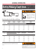
Cast Iron Installation
GENERAL INFORMATION
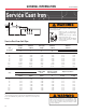
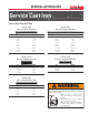
Service Cast Iron
Inside Outside Inside
Diameter Diameter Telescoping Diameter Thickness
Size
A
of Hub
B
of Barrel Length of Barrel of Barrel
Availability
B
T
A J Y B
Nom Min
Service Cast Iron Soil Pipe
2” 0.13 0.34 0.75 0.22 0.10 0.19
3” 0.16 0.37 0.81 0.22 0.10 0.19
4” 0.16 0.37 0.88 0.22 0.10 0.19
5” 0.16 0.37 0.88 0.22 0.10 0.19
6” 0.18 0.37 0.88 0.22 0.10 0.19
8” 0.19 0.44 1.19 0.38 0.15 0.22
10” 0.27 0.53 1.19 0.38 0.15 0.22
12” 0.27 0.53 1.44 0.47 0.15 0.22
15” 0.30 0.58 1.44 0.47 0.15 0.22
Thickness of Hub Distance from
Width of Hub Lead Groove to End, Depth of Lead Groove
Size
A
Hub Body Over Bead Bead Pipe and Fittings
B
S (min) R (min) F(min) P G (min) G (max)
2” 2.94 2.30 2.50 1.96 0.17 0.14
3” 3.94 3.30 2.75 2.96 0.17 0.14
4” 4.94 4.30 3.00 3.94 0.18 0.15
5” 5.94 5.30 3.00 4.94 0.18 0.15
6” 6.94 6.30 3.00 5.94 0.18 0.15
8” 9.25 8.38 3.50 7.94 0.23 0.17
10” 11.38 10.50 3.50 9.94 0.28 0.22
12” 13.50 12.50 4.25 11.94 0.28 0.22
15” 16.95 15.88 4.25 15.16 0.36 0.30
A
Nominal inside diameter.
B
For tolerances, please refer to the chart Dimensional Toler-
ances for Extra Heavy and Service Cast Iron Soli Pipe and
Fittings.
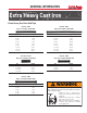
• NEVER test with or transport/store
compressed air or gas in Cast Iron pipe
or fittings.
• NEVER test Cast Iron pipe or fittings
with compressed air or gas.
• ONLY use Cast Iron pipe and fittings
for drain, waste and vent or sanitary
sewer applications.
Testing with or use of compressed air or gas in Cast Iron
pipe or fittings can result in explosive failures and cause
severe injury or death.
Cast Iron pipe and fittings are only intended for DWV
(drain, waste and vent) non-pressure applications. Using
cast iron pipe and fittings in pressure applications could
result in explosive failures, causing serious injury or death
or property damage.
(Telescoping Length)
Laying Length
BJAT
Y
P
G
R
1/8
S
F